Multi-Discipline Supports
User Guide
Hangers : Create an MDS Hanger using a Manufacturer’s Interface : Create a Hanger - Witch Hanger interface
|
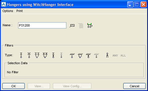
Figure 5:8.
|
|
3.
|
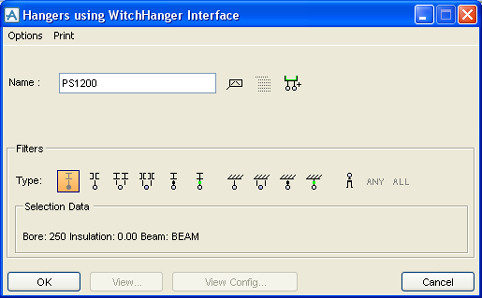
Click on the Filter Type icon for the type of hanger support which is required to be created. Filtering is described in Using the Filters. In this example select the first Filter Icon
|
|
6.
|
Identify the steelwork in the graphical view. The identified steelwork is entered into the Selection Data area in the window, as shown below:
|
|
Figure 5:9.
|
|
7.
|
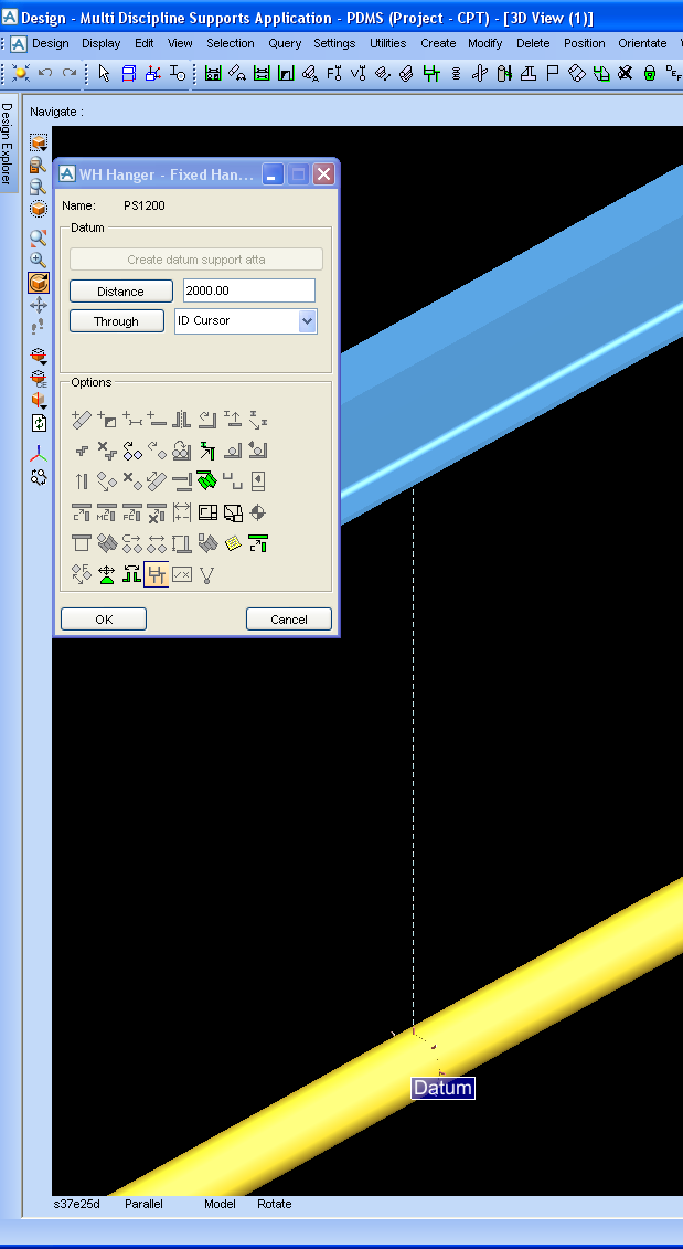
Click OK. A dotted line is drawn in the graphical view between the pipe and the steelwork, and the MDS main hanger elements are created in the database. The window below is also displayed:
|
|
Figure 5:10.
|
|
8.
|
The hanger now needs to be positioned, by either entering a precise distance measurement and clicking Distance, or clicking Through and choosing one of the available options.
|
|
9.
|
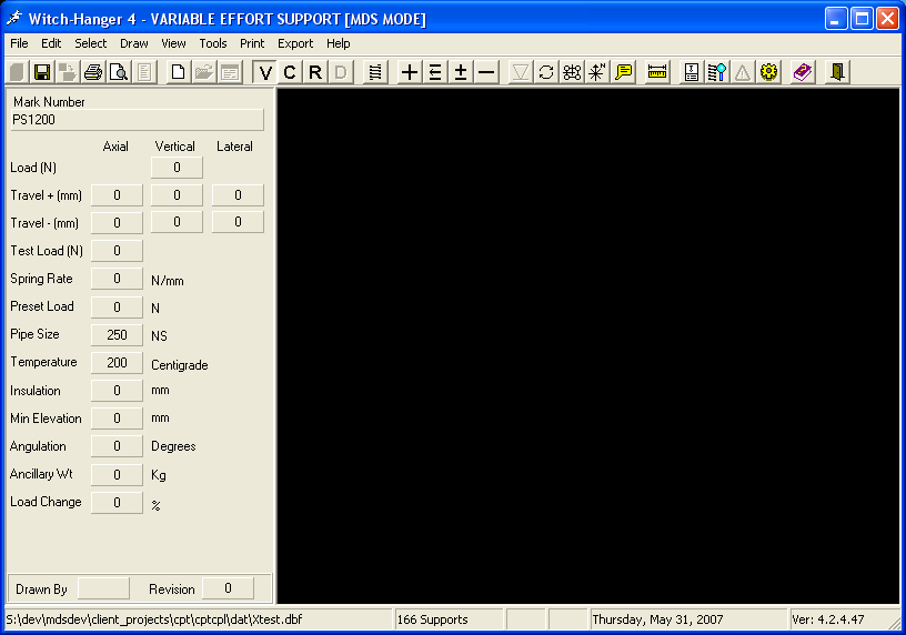
Click OK. The user is automatically taken into the Witch Hanger design software and the following window is displayed:
|
|
Figure 5:11.
|
|
10.
|
Click on the V icon to design a variable support; the following window is displayed:
|
|
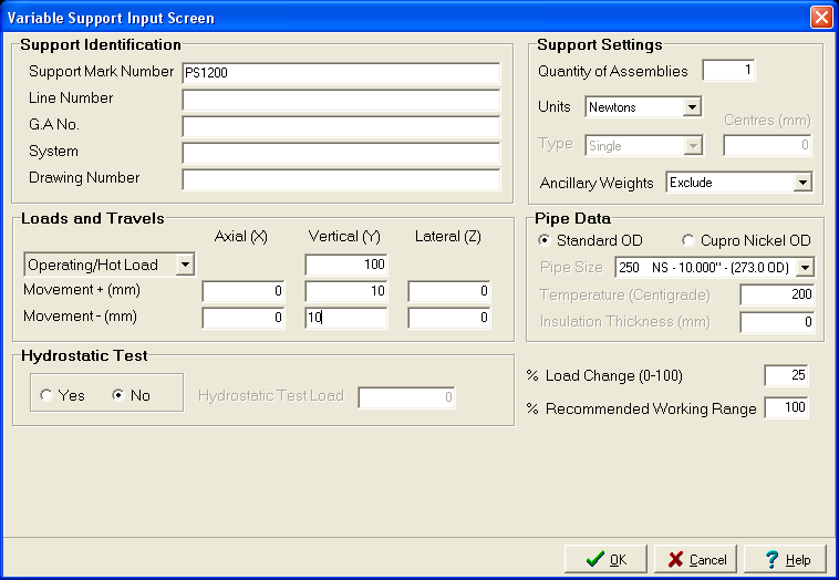
Figure 5:12.
|
|
11.
|
Enter the required Operating/Hot Load value and the positive and negative Movement required for the Axial (X), Vertical (V) and Lateral (Z) directions.
|
|
12.
|
Click OK; the following window is displayed:
|
|
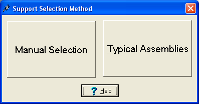
Figure 5:13.
|
|
13.
|
Click Typical Assemblies to display the types of variable hangers available for selection:
|
|
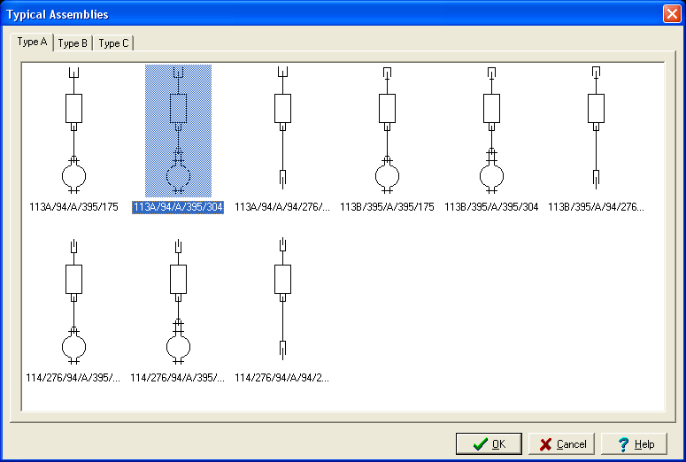
Figure 5:14.
|
|
14.
|
Select the required assembly and click OK. This initialise the hanger design and allows the user to manually set the intermediate hanger elevation using the window shown below:
|
|
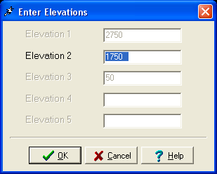
Figure 5:15.
|
|
15.
|
Click OK. The hanger design is displayed in the main Witch Hanger window, as shown below:
|
|
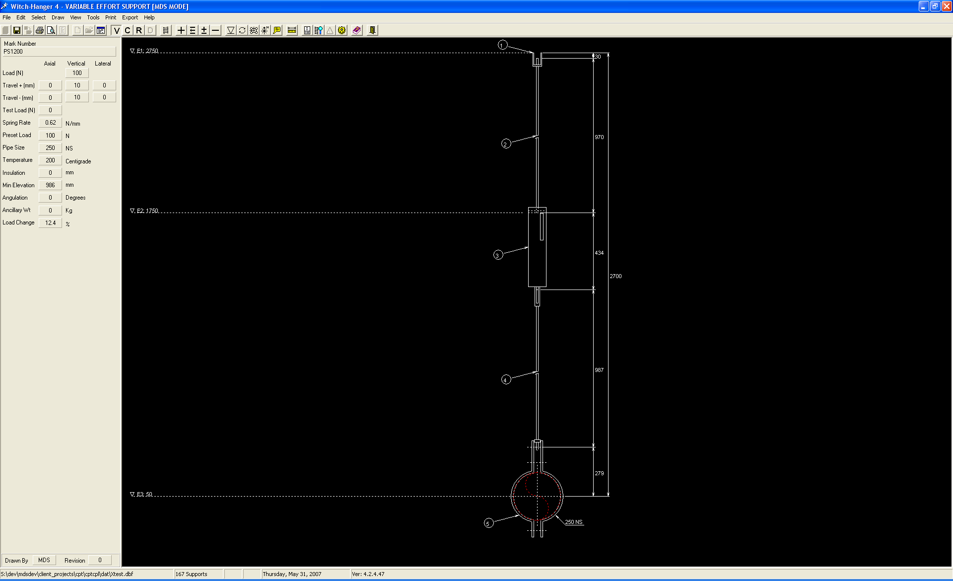
Figure 5:16.
|
|
16.
|
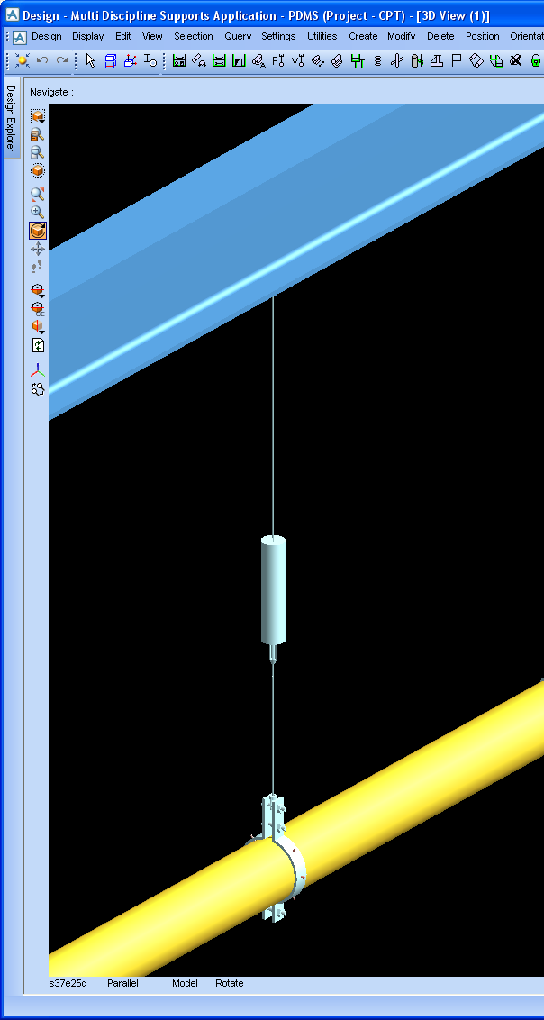
Select the Save icon to save the completed hanger design, exit the Witch Hanger application and return to the MDS application. The hanger data is translated and created into MDS hanger components, as shown in the 3D view.
|
|
Figure 5:17.
|