Multi-Discipline Supports
Administrator Guide
Modifying User Defined Ancillary Geometry
: Geometry Sets
Geometry Sets
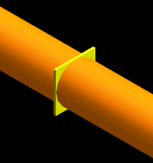
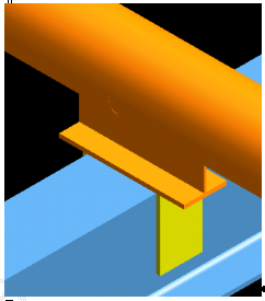
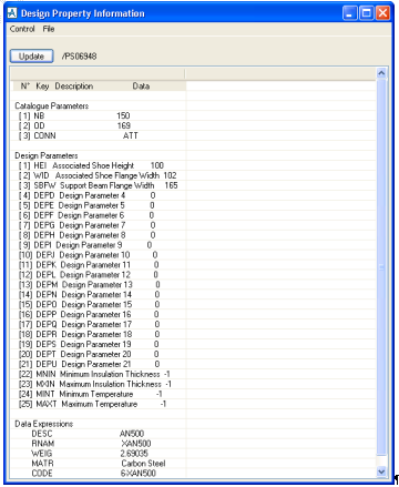
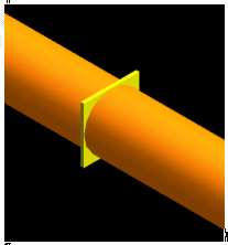
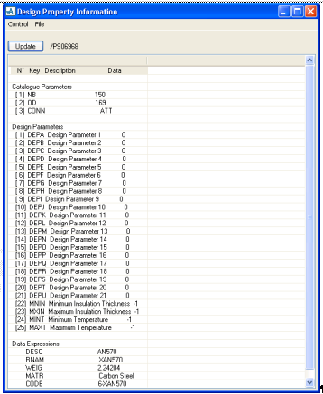
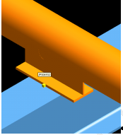
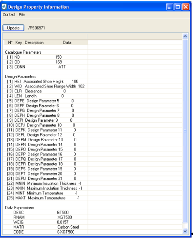
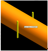
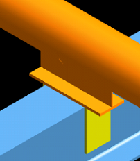
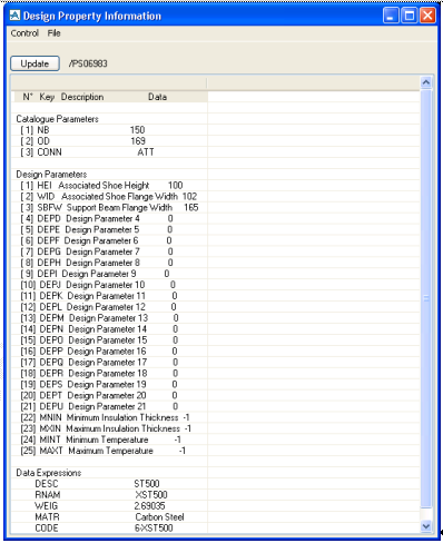
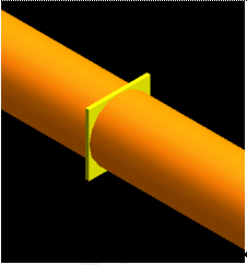
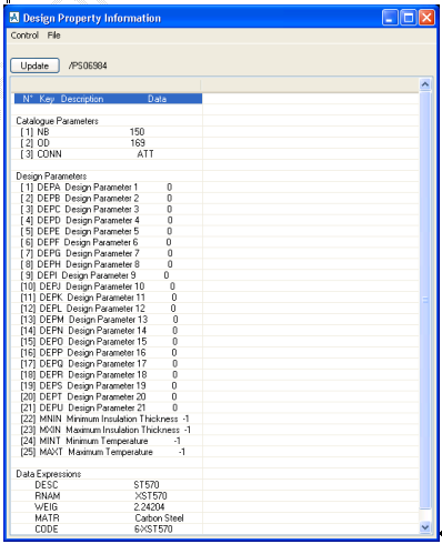
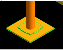
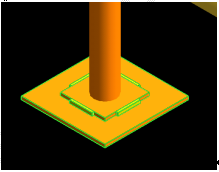
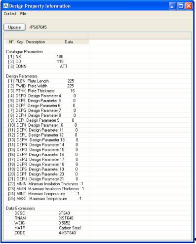
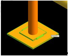
The geometry sets have been created in project MDU. The following diagrams show what has been added and detail any properties that are being used. The
MDS
Administrator can add geometry using these properties if needed and add additional properties as necessary.
AT500 to AT700, BT500 to BT700, LT500 to LT700
Simple Box Representation
This is set to a length of 10, and uses the pipe outside diameter (OD) as the x and y length.
The three standard catalogue parameters have been added, nominal bore (NB), outside diameter (OD) and connection type (CONN) and 25 design parameters have been created. The following are the parameters that have been preset, i.e. to -1. All other design parameters are set to 0 (zero), as shown in the form displayed above.
Number
Description
Dkey
22
Minimum Insulation
MNIN
23
Maximum Insulation
MXIN
24
Minimum Temperature
MINT
25
Maximum Temperature
MAXT
No user editable design parameters have been defined.
AN500 to AN569
Anchor for Shoes
Simple Anchor Representation
These user standards will ask for a pipe shoe to be identified so it will read the shoe parameters HEI (shoe height) and WID (flange width) in order to size the anchor. It will then ask for a section or box to be identified to read the anchor width across the section of box.
The three standard catalogue parameters have been added, nominal bore (NB), outside diameter (OD) and connection type (CONN) and 25 design parameters have been created. The following list the parameters that have been preset, i.e. to -1, 100, 102 and 165. All other design parameters are set to 0 (zero), as shown in the form displayed above.
Number
Description
Dkey
1
Associated Shoe Height
HEI
2
Associated Shoe Flange Width
WID
3
Support Beam Flange Width
SBFW
22
Minimum Insulation
MNIN
23
Maximum Insulation
MXIN
24
Minimum Temperature
MINT
25
Maximum Temperature
MAXT
Design parameters 1, 2 and 3 have been declared as user editable (with an allowable range of 0 to 1000) and default values have been added as shown.
AN570 to AN639
Anchor for Pipes
Simple Box Representation
The three standard catalogue parameters have been added, nominal bore (NB), outside diameter (OD) and connection type (CONN) and 25 design parameters have been created. The following list the parameters that have been preset i.e. to -1. All other design parameters are set to 0 (zero), as shown in the form displayed above.
Number
Description
Dkey
22
Minimum Insulation
MNIN
23
Maximum Insulation
MXIN
24
Minimum Temperature
MINT
25
Maximum Temperature
MAXT
No user editable design parameters have been defined.
GT500 to GT569
Guide for Shoes
Simple Guide Representation
These user standards will ask for a pipe shoe to be identified so it will read the shoe parameters HEI (shoe height) and WID (flange width) in order to size the guide.
The three standard catalogue parameters have been added, nominal bore (NB), outside diameter (OD) and connection type (CONN) and 25 design parameters have been created. The following list the parameters that have been preset, i.e. to -1, 100 and 102. All other design parameters are set to 0 (zero), as shown in the form displayed above.
Number
Description
Dkey
1
Associated Shoe Height
HEI
2
Associated Shoe Flange Width
WID
3
Clearance
CLR
4
Length
LEN
22
Minimum Insulation
MNIN
23
Maximum Insulation
MXIN
24
Minimum Temperature
MINT
25
Maximum Temperature
MAXT
Design parameters 1, 2, 3 and 4 have been declared as user editable (with an allowable range of 0 to 1000) and default values have been added as shown.
GT570 to GT639
Guide for Pipes
Simple Guide Representation
The three standard catalogue parameters have been added, nominal bore (NB), outside diameter (OD) and connection type (CONN) and 25 design parameters have been created. The following list the parameters that have been preset, i.e. to -1 and 0. All other design parameters are set to 0 (zero), as shown in the form displayed above.
Number
Description
Dkey
1
Height
HEI
2
Width
WID
3
Clearance
CLR
4
Length
LEN
22
Minimum Insulation
MNIN
23
Maximum Insulation
MXIN
24
Minimum Temperature
MINT
25
Maximum Temperature
MAXT
Design parameters 1, 2, 3 and 4 have been declared as user editable (with an allowable range of 0 to 1000) and default values have been added as shown.
ST500 to ST569
Stop for Shoes
Simple Stop Representation
These user standards will ask for a pipe shoe to be identified so it will read the shoe parameters HEI (shoe height) and WID (flange width) in order to size the anchor. It will then ask for a section or box to be identified to read the anchor width across the section of box.
The three standard catalogue parameters have been added, nominal bore (NB), outside diameter (OD) and connection type (CONN) and 25 design parameters have been created. The following list the parameters that have been preset, i.e. to -1, 100 102 and 165. All other design parameters are set to 0 (zero), as shown in form displayed above.
Number
Description
Dkey
1
Associated Shoe Height
HEI
2
Associated Shoe Flange Width
WID
3
Support Beam Flange Width
SBFW
22
Minimum Insulation
MNIN
23
Maximum Insulation
MXIN
24
Minimum Temperature
MINT
25
Maximum Temperature
MAXT
Design parameters 1, 2 and 3 have been declared as user editable (with an allowable range of 0 to 1000) and default values have been added as shown.
ST570 to ST639
Stop for Pipes
Simple Box Representation
The three standard catalogue parameters have been added, nominal bore (NB), outside diameter (OD) and connection type (CONN) and 25 design parameters have been created. The following list the parameters that have been preset, i.e. to -1. All other design parameters are set to 0 (zero) as shown in the form displayed above.
Number
Description
Dkey
22
Minimum Insulation
MNIN
23
Maximum Insulation
MXIN
24
Minimum Temperature
MINT
25
Maximum Temperature
MAXT
AN640 to AN700
Anchor for Trunnions
Simple Anchor Representation
The three standard catalogue parameters have been added, nominal bore (NB), outside diameter (OD) and connection type (CONN) and 25 design parameters have been created. The following list the parameters that have been preset. The plate length (PLEN), plate width (PWID) and plate thickness (PTHK) will be obtained from the identified base plate, i.e. to -1. All other design parameters are set to 0 (zero) as shown in the form displayed above.
Number
Description
Dkey
1
Plate Length
PLEN
2
Plate Width
PWID
3
Plate Thickness
PTHK
22
Minimum Insulation
MNIN
23
Maximum Insulation
MXIN
24
Minimum Temperature
MINT
25
Maximum Temperature
MAXT
Design parameters 1, 2 and 3 have been declared as user editable (with an allowable range of 0 to 1000) and default values have been added as shown.
ST640 to ST700
Stop for Trunnions
Simple Stop Representation
The three standard catalogue parameters have been added, nominal bore (NB), outside diameter (OD) and connection type (CONN) and 25 design parameters have been created. The following list the parameters that have been preset. The plate length (PLEN), plate width (PWID) and plate thickness (PTHK) will be obtained from the identified base plate. All other design parameters are set to 0 (zero) as shown in the form displayed above.
Number
Description
Dkey
1
Plate Length
PLEN
2
Plate Width
PWID
3
Plate Thickness
PTHK
22
Minimum Insulation
MNIN
23
Maximum Insulation
MXIN
24
Minimum Temperature
MINT
25
Maximum Temperature
MAXT
Design parameters 1, 2 and 3 have been declared as user editable (with an allowable range of 0 to 1000) and default values have been added as shown.
GT640 to GT700
Guide for Trunnions
Simple Guide Representation
The three standard catalogue parameters have been added, nominal bore (NB), outside diameter (OD) and connection type (CONN) and 25 design parameters have been created. The following list the parameters that have been preset. The plate length (PLEN), plate width (PWID) and plate thickness (PTHK) will be obtained from the identified base plate. All other design parameters are set to 0 (zero) as shown in the form displayed above.
Number
Description
Dkey
1
Plate Length
PLEN
2
Plate Width
PWID
3
Plate Thickness
PTHK
22
Minimum Insulation
MNIN
23
Maximum Insulation
MXIN
24
Minimum Temperature
MINT
25
Maximum Temperature
MAXT
Design parameters 1, 2 and 3 have been declared as user editable (with an allowable range of 0 to 1000) and default values have been added as shown.
1974 to current year.
AVEVA Solutions Limited and its subsidiaries. All rights reserved.