ISODRAFT
Reference Manual
Symbol Keys
: FILT Symbol Keys
FILT Symbol Keys
Component Description
SKEY
Plotted Symbol
P-points
Note
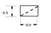
Filter/Strainer -
Straight Through
FI**
1
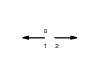
Filter/Strainer - Angle
FA**
1,2
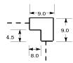
Filter/Strainer - Offset
FO**
1,3,5
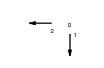
Filter/Strainer -
Return
FR**
1,4
'Y'-type Filter/ Strainer
FY**
1
Notes:
1.
Replace the ** characters in the symbol key with one of the following end condition identifiers:
BW for butt weld
CP for compression
SW for socket weld
FL for flanged
SC for screwed
PL for plain
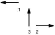
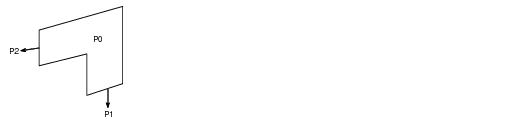
2.
To use this symbol, the p-points must be arranged as shown in the following diagram:
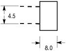
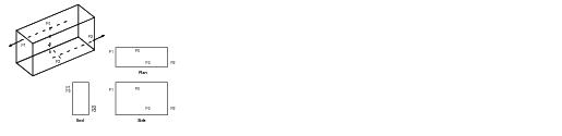
3.
To use this symbol, the p-points must be arranged as shown in the following diagram:
Note:
That the horizontal offset may be zero; i.e. P0, P1, P2 and P3 may be coplanar.
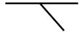
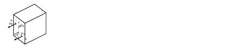
4.
To use this symbol, the p-points must be arranged as shown in the following diagram:
Note:
That P3 is used only for orientation purposes and will have its bore unset. The horizontal offset may be zero; i.e. P0 and P1(and similarly P2 and P3) may be coincident.
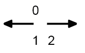
5.
Generic type FILT has a connection reference to facilitate connections to reducers.
If the connection facility is not being used, then an eccentric reducer will have a p-arrive, a p-leave, and a P3 to orientate the flat side.
If the connection facility is to be used, P3 will be the connection p-point and as such must have valid bore and orientation data for the connection. As the flat side can be either in the same direction as the connection or directly opposite, a P9 p-point must be used to give the orientation of the flat side.
1974 to current year.
AVEVA Solutions Limited and its subsidiaries. All rights reserved.