Equipment
User Guide
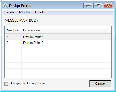
The Design Points window allows the user to create, modify and delete a Design Point.
The name of the currently selected equipment item and a list of defined Design Points display within the Design Points window.
Select the Navigate to Design Point check box to navigate to the selected Design Point in the 3D view.
|
Click Create > Cartesian Point to display the Create - Cartesian Design Point window. Refer to Create Cartesian Design Point for further information.
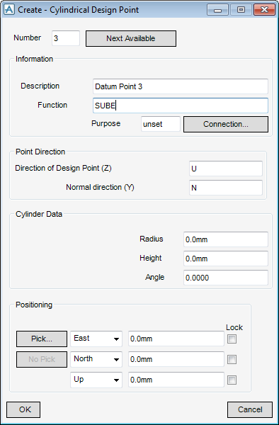
Click Create > Cylindrical Point to display the Create - Cylindrical Design Point window. Refer to Create Cylindrical Design Point for further information.
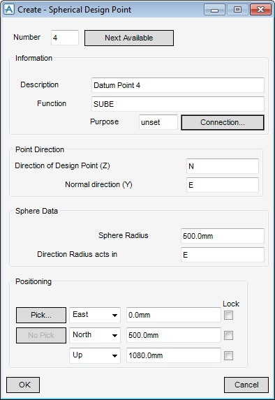
Click Create > Spherical Point to display the Create - Spherical Design Point window. Refer to Create Spherical Design Point for further information.
|
|
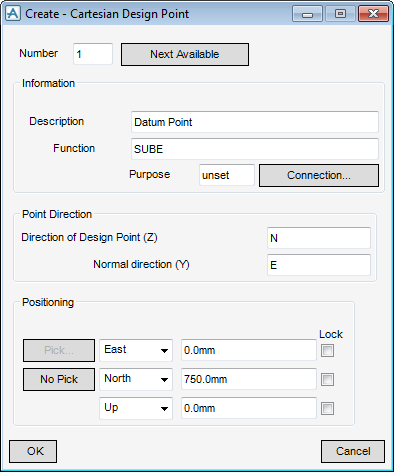
On the Design Points window, click Create > Cartesian Point to display the Create - Cartesian Design Point window.
|
Input a Design Point number into the Number field. Alternatively, select Next Available to display the next available Design Point number by default.
|
|
|
The user can input a description into the optional Description field.
|
|
|
The user can input a function into the optional Function field.
|
|
|
The user can input a purpose into the optional Purpose field.
|
|
|
Input a design point connection direction, for example, input U in the Direction of Design Point (Z) field to direct the design point to face the U axes.
|
|
|
The user is prompted to Define Position (Distance[0]) Snap:
The Positioning Control window displays by default. Refer to Positioning Control for further information.
|
|
|
Select the position axis from the Position drop-down lists, choose from East/West, North/South and Up/Down. The user can then input the explicit position values in the Position fields.
|
|
Click OK to create the Design Point or Cancel to discard any inputs and close the Create - Cartesian Design Point window. The user is returned to the Design Points window.
The Point Connection window allows the user to define a connection type for the Design Point.
On the Create - Cartesian Design Point window, select Connection to display the Point Connection window.
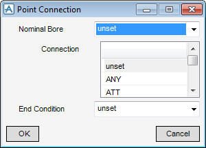
Click OK to apply the connection definitions or Cancel to discard any inputs and close the Point Connection window. The user is returned to the Create - Cartesian Design Point window.
On the Design Points window, click Create > Cylindrical Point to display the Create - Cylindrical Design Point window.
|
Input a Design Point number into the Number field. Alternatively, select Next Available to display the next available Design Point number by default.
|
|
|
The user can input a description into the optional Description field.
|
|
|
The user can input a function into the optional Function field.
|
|
|
The user can input a purpose into the optional Purpose field.
|
|
|
Input a design point connection direction, for example, input U in the Direction of Design Point (Z) field to direct the design point to face the U axes.
|
|
|
The user is prompted to Define Position (Distance[0]) Snap :
The Positioning Control window displays by default. Refer to Positioning Control for further information.
|
|
|
Select the position axis from the Position drop-down lists, choose from East/West, North/South and Up/Down. The user can then input the explicit position values in the Position fields.
|
|
Click OK to create the Design Point or Cancel to discard any inputs and close the Create - Cylindrical Design Point window. The user is returned to the Design Points window.
On the Design Points window, click Create > Spherical Point to display the Create - Spherical Design Point window.
|
Input a Design Point number into the Number field. Alternatively, select Next Available to display the next available Design Point number by default.
|
|
|
The user can input a description into the optional Description field.
|
|
|
The user can input a function into the optional Function field.
|
|
|
The user can input a purpose into the optional Purpose field.
|
|
|
Input a design point connection direction, for example, input U in the Direction of Design Point (Z) field to direct the design point to face the U axes.
|
|
|
The user is prompted to Define Position (Distance[0]) Snap :
The Positioning Control window displays by default. Refer to Positioning Control for further information.
|
|
|
Select the position axis from the Position drop-down lists, choose from East/West, North/South and Up/Down. The user can then input the explicit position values in the Position fields.
|
|
Click OK to create the Design Point or Cancel to discard any inputs and close the Create - Spherical Design Point window. The user is returned to the Design Points window.
The Design Points window allows the user to modify the currently selected Design Point in the list of defined Design Points. The Design Templates application identifies the design point type by default and displays either the Modify - Cartesian Design Point window, Modify - Cylindrical Design Point window or Modify - Spherical Design Point window.
To modify the currently selected Cartesian Design Point, on the Design Points window, select Modify > Point to display the Modify - Cartesian Design Point window.
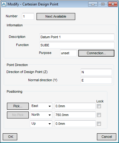
The functionality of the Modify - Cartesian Design Point is identical to that described in Create Cartesian Design Point. Refer to Create Cartesian Design Point for further information.
To modify the currently selected Cylindrical Design Point, on the Design Points window, select Modify > Point to display the Modify - Cylindrical Design Point window.
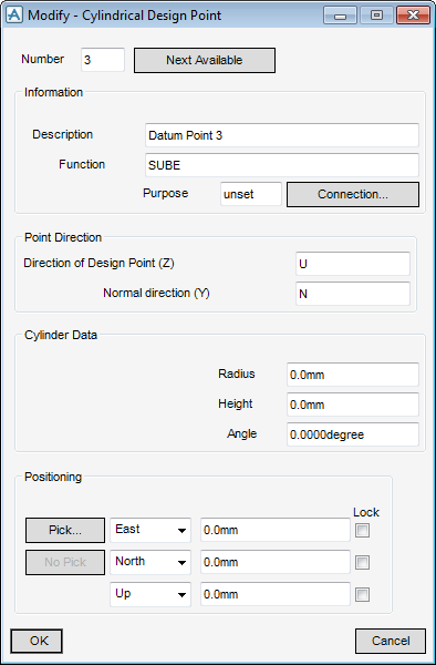
The functionality of the Modify - Cylindrical Design Point is identical to that described in Create Cylindrical Design Point. Refer to Create Cylindrical Design Point for further information.
To modify the currently selected Spherical Design Point, on the Design Points window, select Modify > Point to display the Modify - Spherical Design Point window.
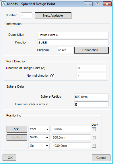
The functionality of the Modify - Spherical Design Point is identical to that described in Create Spherical Design Point. Refer to Create Spherical Design Point for further information.
The Design Points window allows the user to delete the currently selected Design Point from the list of defined Design Points. Alternatively the user can delete all Design Points for the currently selected equipment item.
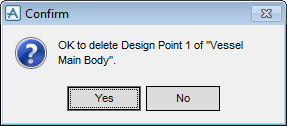
To delete all Design Points from the currently selected equipment item, on the Design Points window, select Delete Point Set to display the Confirm window.
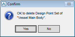
Click Yes to delete all Design Points from the currently selected item or Cancel to discard the Confirm window. The DPSE element is deleted from the Model Explorer.
To delete the currently selected Design Point in the list of defined Design Points, on the Design Points window, select Delete Point to display the Confirm window.