DRAW Reference Manual
Drawing the Design : Hidden Line Representation
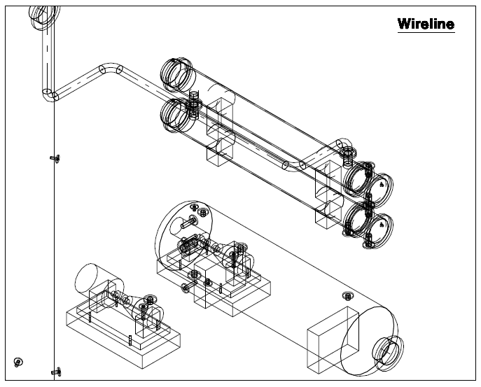
The VTYP (view type) command controls the hidden-line representation of displayed pictures. Six possible VTYP settings are provided. These give progressively greater graphical accuracy at the expense of increasing processing requirements. This facility allows you to produce preliminary and intermediate drawings (where graphical accuracy may be of secondary importance) quickly, leaving only finished drawings to incur the greatest processing overhead. The default VTYP setting is WIRELINE, which gives a conventional wireline picture. Refer to Figure 3:6.: Typical Wireline View for further information.
|
Figure 3:6.
|
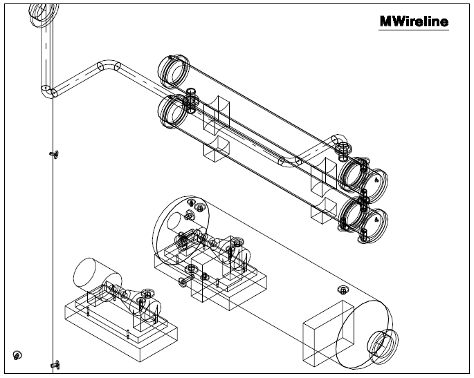
Modelled Wireline representation gives slightly greater realism by blending the intersection of primitives, but without incurring the computational overheads of removing hidden lines. Refer to Figure 3:7.: Typical Modelled Wireline View for further information.
|
Figure 3:7.
|
Wireline Hidden Line Removed representation produces a View where hidden lines are removed from individual significant elements (EQUI, SUBS, etc) but not from items hidden behind them. Refer to Figure 3:9.: Typical Local Hidden Lines Removed View for further information.

|
Figure 3:8.
|
Local Hidden Line representation gives a picture where hidden lines are removed from individual significant elements (EQUI, SUBS etc), but not from items hidden behind them. Refer to Figure 3:9.: Typical Local Hidden Lines Removed View for further information.

|
Figure 3:9.
|
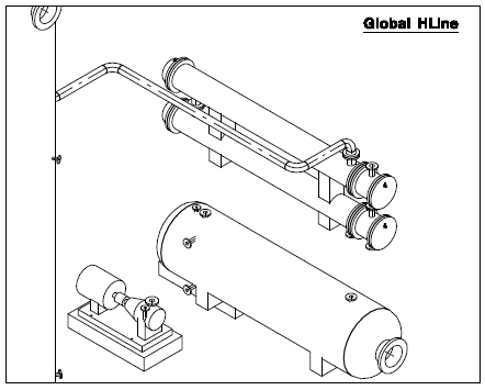
Global Hidden Line representation gives a picture where all hidden lines are removed. Refer to Figure 3:10.: Typical Global Hidden Lines Removed View for further information.
|
Figure 3:10.
|
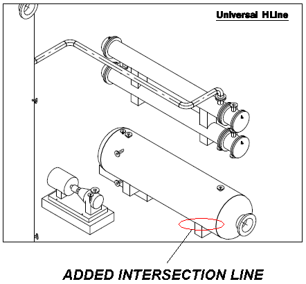
Universal representation (refer to Figure 3:11.: UNIVERSAL VIEW Type for further information) gives a picture where all hidden lines are removed (as in Global HLR), but in addition intersection lines between clashing significant elements (e.g. EQUI and STRU or SUBS and SUBS) are generated. Whether you will need to use this View type will depend on the way in which you have created the model. The need for VTYP UNIVERSAL will be greater if the model is composed of a large number of significant elements each with a small number of primitives, rather than vice versa. It is also more likely to be needed in non-orthogonal Views, where missing intersection lines are most noticeable.
|
Figure 3:11.
|