Common Functionality
User Guide
Data Check : User Grid Systems
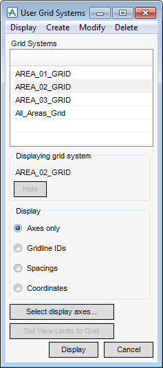
The Grid Utility is available on the 3D View tab, in the Aids group, click User Grid Systems to display the User Grid Systems window.
|
Features a Hide option which allows the user to hide the grid system currently displayed in the view.
The hidden grid system can be re-displayed, click Display at the bottom of the window. |
|
|
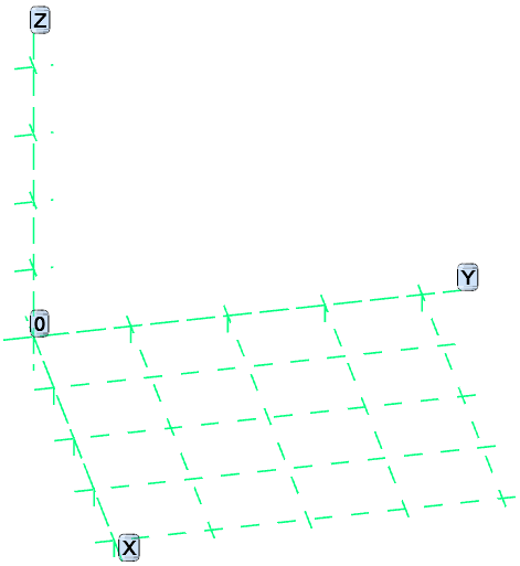
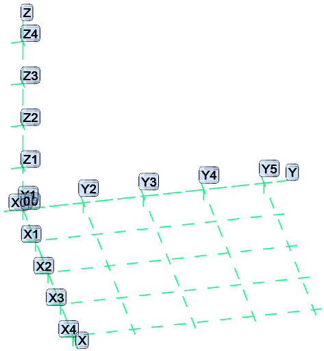
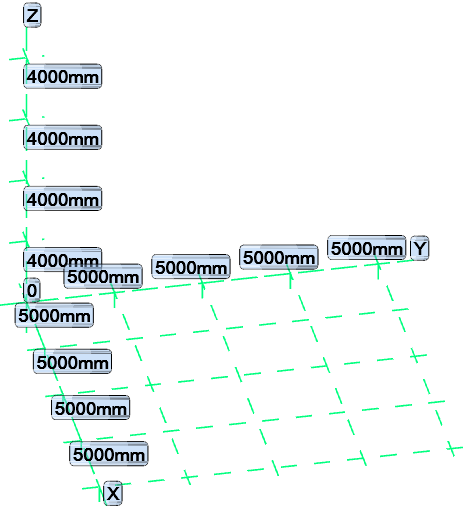
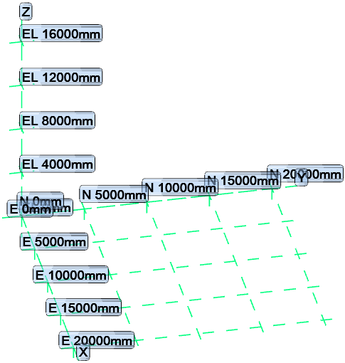
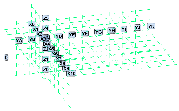
The options available in the frame allow the user to label the grid in the view in various ways: Axes only; Gridline IDs; Spacings; and Coordinates.
|
|
|
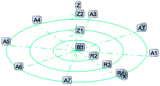
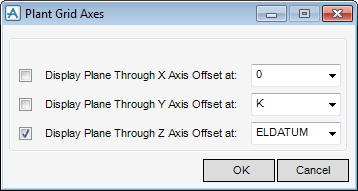
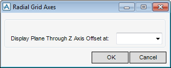
Displays either the Plant Grid Axes window for a rectangular grid or the Radial Grid Axes window for a radial grid. Both windows are used to select which planes are drawn for the current grid system.
|
|
 |
|
 |
|
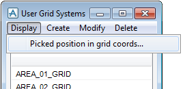
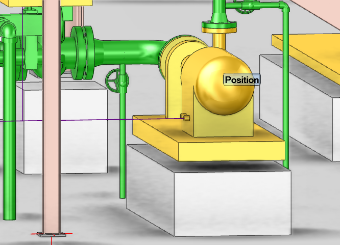
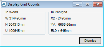
Select Display > Picked position in grid coords activates the pick, which uses the standard position window so any element, ppoint, graphic can be picked.
|
Gives options for displaying either the Reference 3D Rectangular Grid or Reference 3D Radial Grid windows. These allow the user to create new grid systems, which can then be saved to the database as Grid Systems.
|
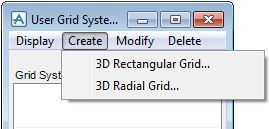
To create a 3D Rectangular Grid, select Create > 3D Rectangular Grid.
The Reference 3D Rectangular Grid creation/modification window displays:
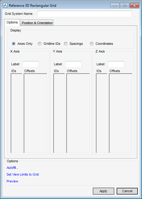
With the Options tab selected, the following are available:
|
Features four options for selecting how the grid is labelled in the view: Axis only; Gridline IDs; Spacings and Coordinates.
|
|
|
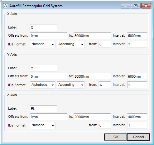
Displays the Autofill Rectangular Grid System window which gives a set of default values in the X Axis, Y Axis and Z Axis panels.
|
To create a 3D Radial Grid, select Create > 3D Radial Grid, the Reference 3D Radial Grid multi-function window displays:
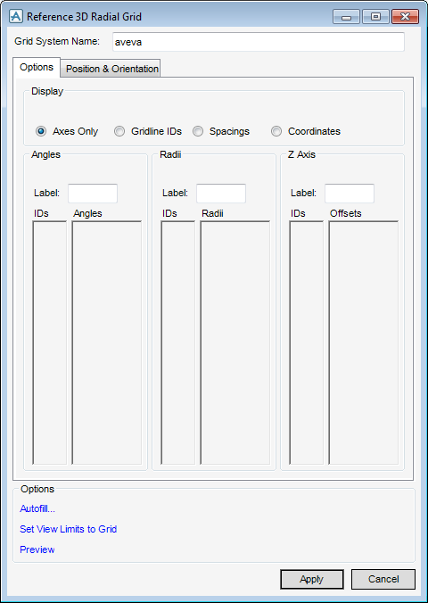
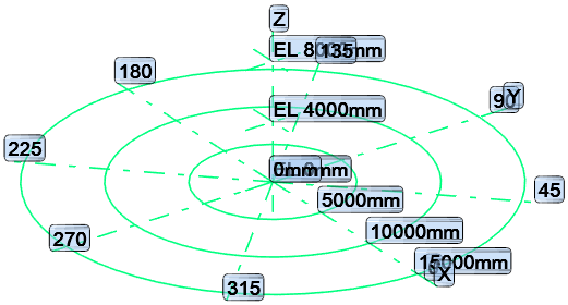
The Reference 3D Radial Grid window is similar to the Reference 3D Plant Grid window except that the X Axis and Y Axis frames are replaced by Angles and Radii frames respectively. IDs are entered for the gridlines, with corresponding Angles, Radii and Offsets entered in the appropriate columns.
|
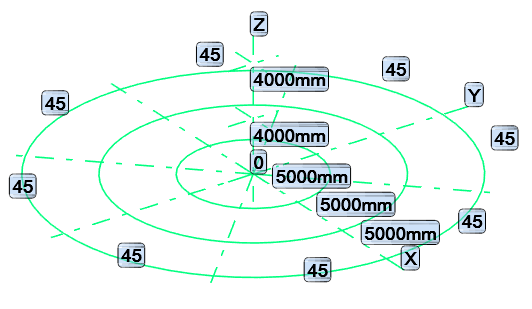
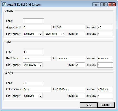
Displays the Autofill Radial Grid System window which offers a set of default values in the Angles, Radii and Z Axis panels.
|
The Set View Limits to Grid, Preview and Save options, together with the Name text box and Position & Orientation tab on the Reference 3D Radial Grid window all operate in a similar manner to the equivalent functions on the Reference 3D Rectangular Grid window.
|
Gives the option of modifying the Selected Grid System.
|
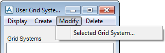
To modify a particular grid system, select it in the Grid Systems scrollable list and select Modify > Selected Grid System.
The appropriate Reference 3D Grid multi function window displays, which is used to modify the selected grid system. The modified grid system can then be saved to the database in the usual manner.