Common Functionality
User Guide
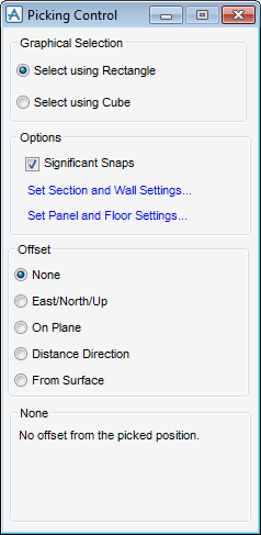
Settings : Picking Control
On the Project tab, click Options, click Views, click Picking Control to display the Picking Control window.
 |
Significant Snaps: If this check box is selected, the significant snap points, as defined on the Snap Settings window (Sections & Walls and Panels & Floors tabs) is picked.
The Offset options specify different types of offset which is applied to a picked position. The options are:
|
Allows the user to specify a 3D offset. East/North/Up text fields are displayed at the bottom of the Picking Control window, enabling the user to specify the required 3D offset.
|
|||||
|
|||||
|
Allows the user to specify an offset distance normal to the picked plane using the Distance text field displayed at the bottom of the Picking control window.
|
|
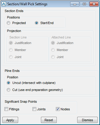
If Projected is selected, the Projection pane becomes active, the user has to determine which control lines of the section are projected to an intersection, select one of the following for Section Line and Attached Line:
|
|||||||
|
Pline Ends Positions determines how the ends of plines are to be defined at end preparations.
Select Uncut (intersect with cutplane) to set the position at the intersection of the pline and the cut plane is returned.
Select Cut (use end preparation geometry) to set the point at which the pline is cut and by any negative geometry of the joint is used.
|
|||||||
|
|||||||
|
Click to Apply the current settings.
|
|||||||
|
Click to Reset to previous settings.
|
|||||||
|
Click to Discard any changes.
|
|
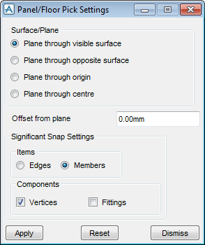
The Items setting determines how the boundary of the panel is to be interpreted.
Select Edges, the panel is interpreted as a set of lines which define its edges at the derived plane.
Select Members, all components of the boundary loop (vertices) and any fittings is considered and snapped to.
The Components settings determine which elements within a panel are to be considered when snapping. Select Vertices check box and/or Fittings check box.
|
|
|
Click to Apply the current settings.
|
|
|
Click to Reset to previous settings.
|
|
|
Click to Discard any changes.
|