Common Functionality
User Guide
View Design : Clipping
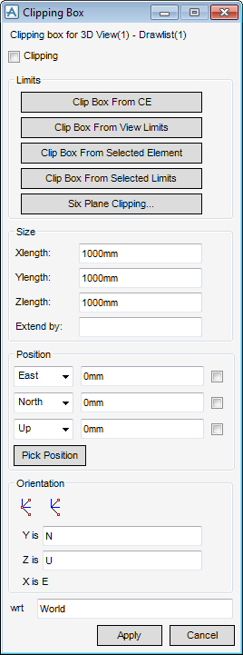
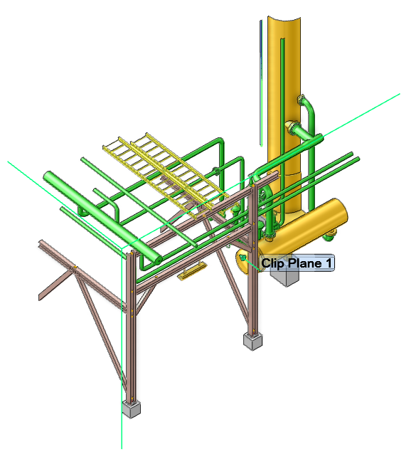
Clipping allows the user to display only the parts of the model which fall inside a clipping box. On the 3D View tab, in the Clip and Cap group, click Define to display the Clipping Box window.
|
Select the Clipping check box to toggle clipping on and off
|
|
|
Allows up to six individual planes to be defined to clip the model. Refer to Six Plane Clipping for further information.
|
If a clipping box has previously been defined its dimensions and origin are displayed on the Clipping Box window, if not, a default sized box is placed at the origin of the view. The current settings for the box are displayed in the 3D View as a box, in the default aid line colour.
The Clipping Box window allows the user to define a new clipping box by either:
|
•
|
Enter the dimensions and co-ordinates of the origin (centre) directly into the text- boxes on the Clipping Box window. The user can use the drop-down list boxes to set the East/West, North/South and Up/Down axes as necessary.
|
|
•
|
Enter the dimensions directly into the text-boxes on the Clipping Box window, and then select Pick Position to pick the required origin in the 3D View with the cursor.
|
|
Note:
|
The Clipping Box window displayed in the 3D View is automatically updated with the picked co-ordinates.
|
The user can use the EDG facilities on the Positioning Control window to select the type of item to be picked in the 3D View, and the mode the software uses to derive the point, and then click Apply.
The user can change the orientation of the clipping box, by defining a plane through which it passes. The icons at the top of the Orientation pane allow the user to define a plane by picking either three explicit points or two points, the third point is taken as the current working plane. Alternatively, the user can edit the Y is and Z is text boxes, to set the orientation of the clipping box.
Click Cancel when satisfied with the settings.
On the 3D View tab, in the Clip and Cap group, click Clipping to make the settings take effect in the 3D view.
|
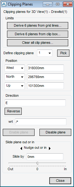
Enables a clipping plane to be aligned, for example, on a item such as a panel or beam, which is picked from the 3D View. The system is then automatically fill in the Position and Direction fields based on the position and orientation of the picked item.
|
|
The clipped volume can then be finely adjusted if necessary, use the Slide plane out or in pane at the bottom of the window to slide the selected plane in or out.
Planes can be automatically defined based on the clipping box, for example clipping the CE, and then adjust individually. Planes can also be defined by selecting grid lines from a grid system. From the Limits pane, click Derive 6 planes from grid lines to display the Clip from Grid window.
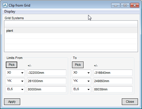
The Grid Systems list shows the available grid systems for the project. When one of these is selected, the lower half of the window changes to reflect the grid system selected.
Individual grid lines to delimit the clipped volume can be selected from the Limits From and To drop-down option lists, or the nearest grid lines to two picked positions can be automatically selected, click Pick. Positive or negative offsets (in mm) relative to the grid lines can be entered into the +/- text fields.
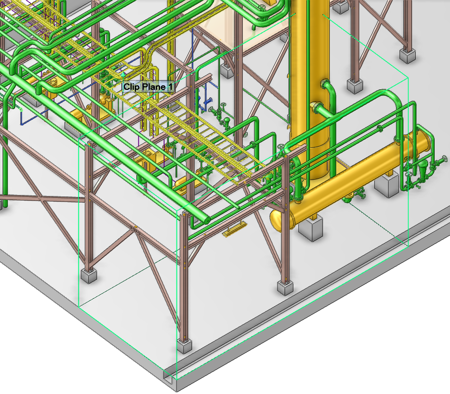
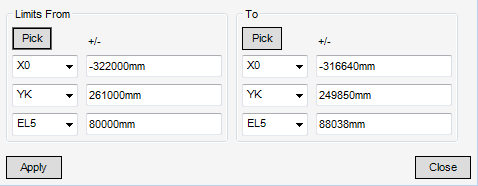
Click Apply to apply the clipping planes to the 3D view:
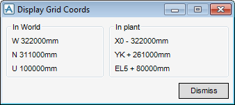
To assist in selecting the appropriate grid lines for clipping, any position can be picked to display it in the World and Grid Coordinates. From the Clip From Grid window select Display > Picked position in grid coords to the Display Grid Coords window.
To control if the caps are added, on the 3D View tab, in the Clip and Cap group, click Capping to set cap on or off. The default is for capping to be off.