Catalogues and Specifications
User Guide
Additional Tools
:
Electrical
: Cable Node Representation
Cable Node Representation
Use the Create Category for Node Representation window when the user is required to define the necessary representation of the Cable Nodes in design, which will eventually be drawn on drawings as symbols.
To create a Cable Node Representation select
Create > Category for Cable Node Representation
from the main window drop-down.
Enter a
Name
and set the
Purpose
to REPR.
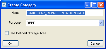
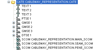
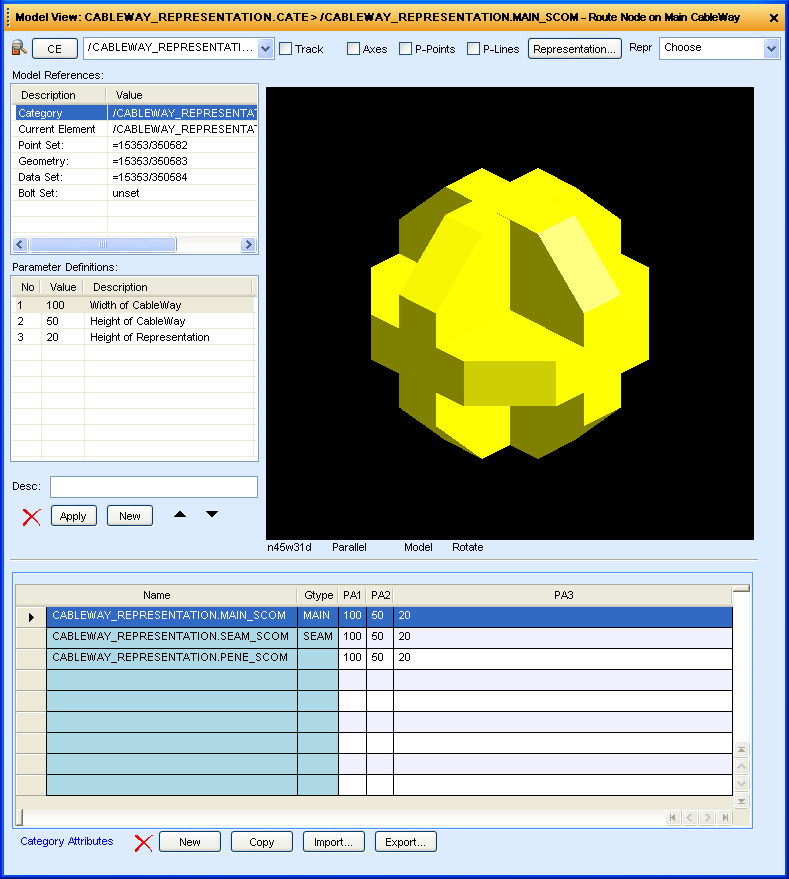
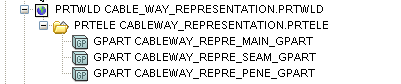
Click
OK
to create the following database hierarchy and display the Category window.
Once defined all elements can then be used in other catalogue element structures, for example GPARTS, TABGRO and subsequently used in MODEL using appropriate selection techniques.
Elements would be defined as in the example shows above, the geometry is defined to make the symbol as the user wishes to see it eventually in design.
Once defined as SCOM elements, it would be then required to create GPART Family, example.
The references here would then point to the previous SCOM elements defined, the CABLE application in MODEL uses the GPART as reference for the representation of the desired element types, in this case, MAIN, SEAM and PENE elements.
1974 to current year.
AVEVA Solutions Limited and its subsidiaries. All rights reserved.