Catalogues and Specifications
User Guide
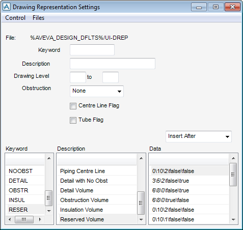
General Application Tools
:
Settings
: Drawing Representation Settings
Drawing Representation Settings
The Drawing Representation Settings window lets a system administrator define the appearance of a component, as displayed in a 3D graphical view depending on the following drawing representation settings:
•
The range of drawing levels to be shown
•
The obstruction level
•
The centreline flag
•
The tube flag
Select
Settings > Representation Rules
from the main menu to display the
Drawing Representation Settings
window.
The user can define representation types, each corresponding to a given combination of these representation settings. Users can then reference such a type to change the appearance of a displayed component.
A set of sub forms show all the representation types currently defined, while the upper part of the main window allows the user to edit the lists by adding, removing or modifying individual entries.
The File entry near the top of the window shows where the current type set, as listed on the window, is stored.
Each representation type is defined by the following settings:
•
A keyword
•
A description
•
A drawing level range
•
An obstruction level
•
The centreline flag
•
The tube flag.
Enter a value in each field pressing
Enter
on the keyboard after each value.
Note:
Each input field will initially appear yellow and change to white when populated. Be sure to press Enter on the keyboard after each value is entered to commit that value.
Above the Data sub window select one of the following values to add a rule to the list:
Insert After
Insert Before
Copy
Replace
Cut
Refer to
Drawing Representation Settings
for further information.
1974 to current year.
AVEVA Solutions Limited and its subsidiaries. All rights reserved.