Cable Design
User Guide
CableTray Design : Cabletray Volume
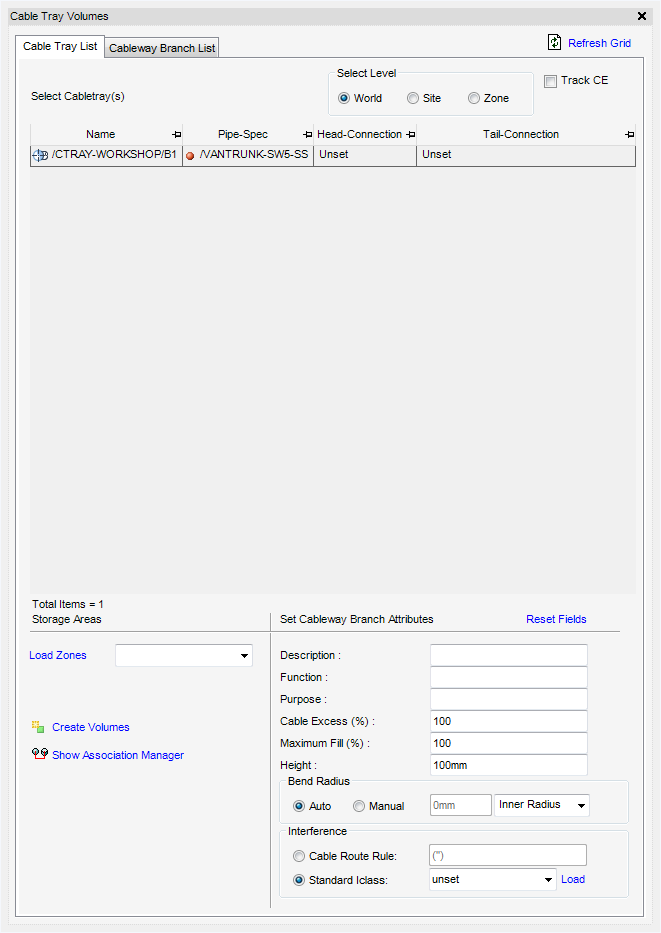
The Cable Tray Volumes window allows the user to select an existing cabletray and create volumes with dimensions extracted from the tray members. Additionally, the user can also select the zone where they would like to create new elements. The user can also set some cableway branch attributes.
On the Cabling System tab, in the Create group, click Cableway, select Cable Tray Volume from the list to display the Cable Tray Volumes window.
|
Clicking Refresh Grid re-displays either grid to reflect any changes made that are not updated automatically.
|
|
The Cable Tray Volumes window lists the cable trays from the current zone and also displays the Head Connection and Tail Connection of each branch. Using the Select Level radio buttons the user can choose to switch between World, Site or Zone levels in order to load trays for the selected level.
|
Displays a Save As window which allows the user to navigate to a location and name the exported Excel file.
|
|
Under Storage Areas the user can select the Zone where they want to create the CWAY/CWBRANCH elements. Clicking Load Zones will populate a list of the available zones for the current element in the hierarchy.
Using the Set Cableway Branch Attributes fields, the user can set some attributes prior to creating the volumes. Clicking Reset Fields resets the values for attributes back to the default settings.
The Bend Radius can be set to Auto or Manual by selecting a radio button. If set to Manual a bend radius must be entered in the field.
To create the volumes, select the required elements from the list and click Create Volume. To create the volumes, an association group with the purpose set to TBAS dedicated to store associations between old cabletray elements and new cabletray elements must exist. If the association group does not exist, an error message is displayed informing the user to create the required association group. When the user clicks OK the Organise Association Store window is displayed which allows the user to create the required association group.
When the association group exists a Confirm window is displayed requesting the user to confirm cableway volumes for the selected cabletray branches are to be created.
|
|
|
|
|
|
Select from the drop-down menu the type of cable to be routed through the cableway. The user can input its own values or click Load, to load interference values from a database.
|
|
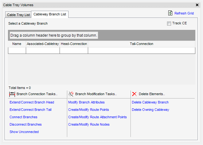
The Cableway Branch List tab displays all the volumes that have been created with their Associated-Cabletray, Head Connection & Tail Connection attributes.
|
Displays the Cableway Branch Modify Tasks window, refer to Modify Cableway Branch for further information.
|
|
|
Displays a Save As window which allows the user to navigate to a location and name the exported Excel file.
|
|
Allows the user to connect the Head of the selected Cableway branch to another branch. When clicked, the user is prompted to pick on the branch segment where the branch head should connect to. Once picked it moves the head position of the selected branch to the picked position on the picked branch. A RATTA will automatically be created where the branches meet.
Allows the user to connect the Tail of the selected Cableway branch to another branch. When clicked, the user is prompted to pick on the branch segment where the branch tail should connect to. Once picked it moves the tail position of the selected branch to the picked position on the picked branch. A RATTA will automatically be created where the branches meet.
Allows the user to connect two cableway branches. When clicked the user is prompted to Pick first branch and then second branch. Clicking Yes on the confirm dialogue form connects the two branches. A RATTA will automatically be created where the branches meet.
Allows the user to display, in the graphical view, Unconnected labels on branch ends with unset connection references. When clicked the link changes to Hide Unconnected which when clicked removes the Unconnected labels from the graphical view.
Displays the Cableway Branch Modify Tasks window. Refer to Modify Cableway Branch for further information.
Displays the Define Path/Route Tasks window with mode set to Creation as default. Refer to Define the Path/Route for further information.
Displays the Route Attachment Points Create Tasks window with mode set to Creation as default. Refer to Create Route Attachment Points for further information.
Displays the Route Node Create Tasks form with mode set to Creation as default. Refer to Create Route Node for further information.