Cable Design
User Guide
CableTray Design : Cable Tray Material Elements
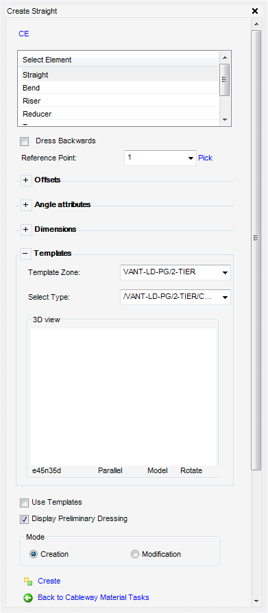
Depending on the element selected from the Select Element part of the window, will dictate which window is displayed. For example the selection of the Reducer element results in the Create Reducer window being displayed. User input will vary depending upon the material element selected. The window for the Straight element is displayed as the default. All the tasks that a user would carry out with creation or modification of cable tray material elements are initiated from the create element window.
The Cable Design User Guide only includes a description for the default (Create Straight). The information can be applied to the same processes that are used to create all other types of cable tray material elements.
Referring to the Cabling hierarchy, a cable tray material element must reside below an existing cable tray material main element (CTMRL). For a detailed explanation of creating an cable tray material element, refer to Cable Tray Material Elements.
To create a Cable Tray Material Element, on the Cabling System tab, in the Create group, click Material, select Material Element from the list to display the default Create Straight window.
|
Note:
|
The user can specify in which direction the material elements are added to the cableway branch, select Dress Backwards to reverse the direction.
To position the origin of the material elements, from Reference Point drop-down menu, select the required reference point or select Pick, the user will be prompted to Pick on the segment which CTSTRA should be placed: In both cases the Along Route (Zdis) field is automatically populated.
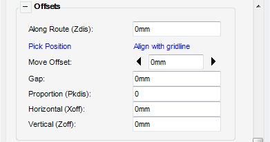
The Offsets part of the window of the Create window, allows the user to position the material element at an offset position.
|
Select Pick Position, the user is prompted to Pick define position (Snap) Snap: in the 3D view to position the material element at the offset.
|
|
|
Select Align with gridline, the user is prompted to Pick Grid to define position: in the 3D view the user can align the picked point with a gridline.
|
|
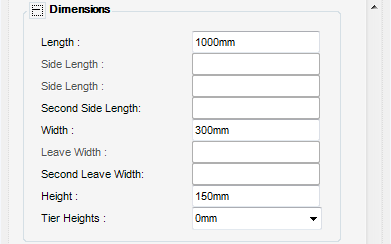
The Dimensions part of the Create window allows the user to view and input the material elements dimensions, some will be automatically populated by the cabling specification.
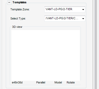
The Templates part of the Create window, allows the user to select a template for the material element and display the element in the 3D view.
|
Select Use Templates to use the selected template for the cable tray material element.
|
|
|
Allows options of Creation or Modification to be selected. After creating a material element, selecting the Modification button displays the corresponding Modify window.
|
|