Stairs Ladders and Handrails
Administrator Guide
Assemblies : Create Rung Ladder Assembly
To create a Rung Ladder Assembly element make sure the correct Structure element is selected in the Assemblies part of the SLH Administration Tasks window.
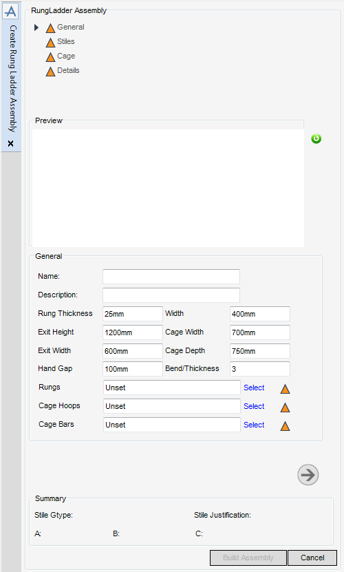
To create a Rung Ladder Assembly element, from the Assemblies part of the SLH Administration Tasks window, click Create next to the Rung Ladder drop-down list to display the Create Rung Ladder Assembly window.
|
Note:
|
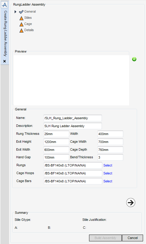
All mandatory parts of the Create Rung Ladder Assembly window are indicated with an amber triangle. The SLH application replaces the amber triangle with a green tick when the Create Rung Ladder Assembly window has been populated with the required data.
|
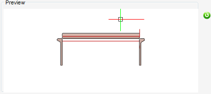
The Preview part of the Create Rung Ladder Assembly window displays throughout the creation process. The SLH application updates the Preview display each time the administrator clicks Next or Back.
The Summary part of the Create Rung Ladder Assembly window displays throughout the creation process. The SLH application updates the Summary display each time the summary data is changed.
The General part of the Create Rung Ladder Assembly window displays by default, the administrator can name, describe and define the new Rung Ladder Assembly element.
|
The functionality available from the Rungs window is identical to that available from the Top Rail Specification window. Refer to Handrail Profile Specification for further information.
|
|
|
The functionality available from the Cage Hoops window is identical to that available from the Top Rail Specification window. Refer to Handrail Profile Specification for further information.
|
|
|
The functionality available from the Cage Bars window is identical to that available from the Top Rail Specification window. Refer to Handrail Profile Specification for further information.
|
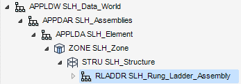
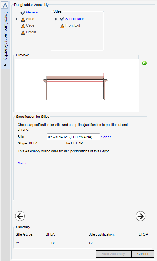
Click Next to display the Specification for Stiles part of the Create Rung Ladder Assembly window. Refer to Stiles Specification for further information. The Assembly element displays in the Model Explorer and the 3D view.
The Specification for Stiles part of the Create Rung Ladder Assembly window allows the administrator to define the stile specification and p-line justification for the Rung Ladder Assembly.
|
The functionality available from the Select Stile window is identical to that available from the Top Rail Specification window. Refer to Handrail Profile Specification for further information.
|
|
|
Click MIrror to mirror the stringer of the Rung Ladder.
|
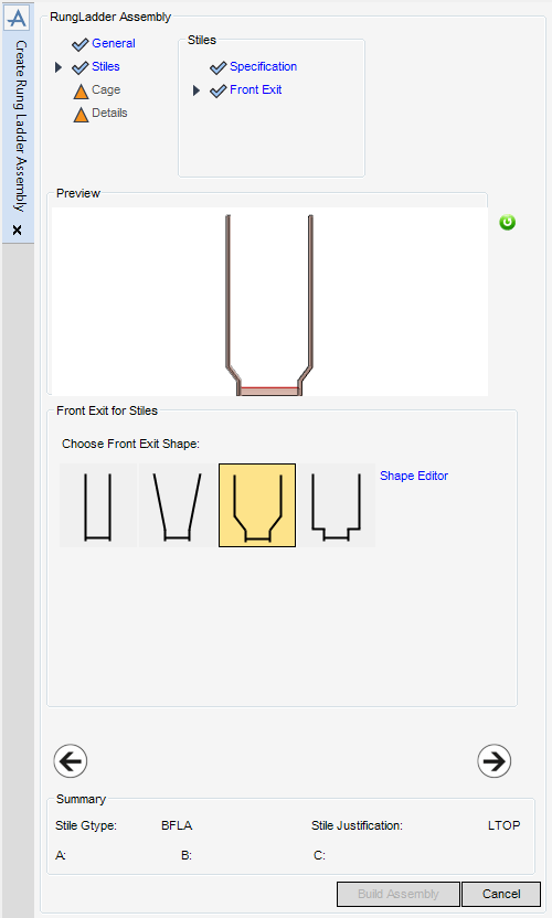
Click Next to display the Front Exit for Stiles part of the Create Rung Ladder Assembly window. Refer to Stiles Front Exit for further information.
The Front Exit for Stiles part of the Create Rung Ladder Assembly window allows the administrator to select or define the front exit shape for the Rung Ladder Assembly.
The administrator can select a Front Exit Shape from the display. Alternatively, the administrator can modify a selected shape with the Shape Editor. Refer to Front Exit Shape Editor for further information.
Click Next to display the Stile Connection for Cage part of the Create Rung Ladder Assembly window. Refer to Cage Stile Connection for further information.
Click Back to return to the Specification for Stiles part of the Create Rung Ladder Assembly window.
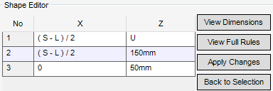
The Shape Editor part of the Create Rung Ladder Assembly window allows the administrator to specify the front exit shape for the Rung Ladder Assembly.
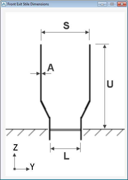
The X column defines the horizontal offset of the left stile. The Z column defines the vertical offset. The administrator can modify the values to define the new shape.
To visualise the dimensions of the shape, click View Dimensions to display the Front Exit Style Dimensions window.
The administrator can view all Rules associated with the shape, click View Full Rules to display the Stiles (Front Exit) Rules window.
Click Apply Changes to accept the changes made to the shape.
Click Back to Selection to discard any inputs and return to the Front Exit for Stiles part of the Create Rung Ladder Assembly window.
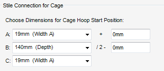
The Stile Connection for Cage part of the Create Rung Ladder Assembly window allows the administrator to define the dimensions for the Cage Hoop Start Position.
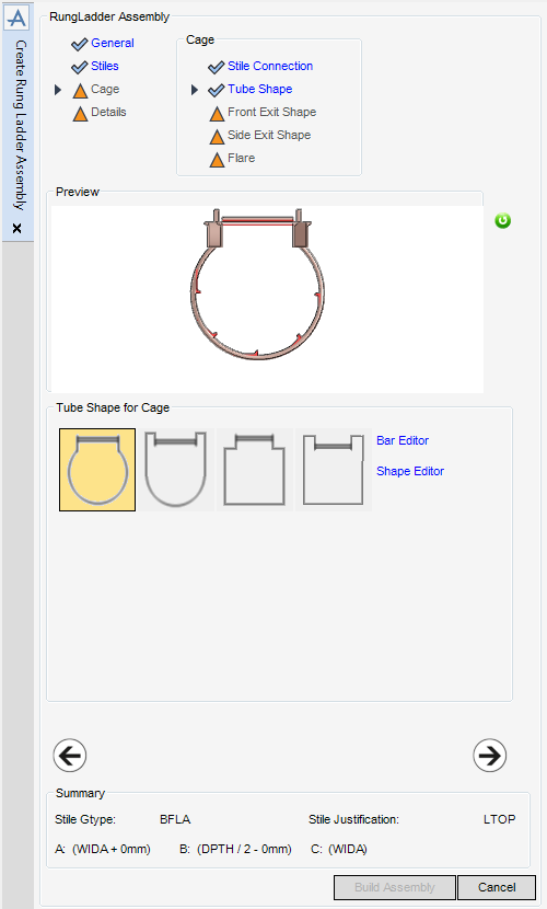
The Tube Shape for Cage part of the Create Rung Ladder Assembly window allows the administrator to select or define the tube shape for the Rung Ladder Assembly.
The administrator can select a Tube Shape from the display. Alternatively, the administrator can modify a selected shape with the Bar Editor (refer to Tube Shape Bar Editor for further information) and the Shape Editor (refer to Tube Shape Editor for further information).
Click Next to display the Front Exit Shape for Cage part of the Create Rung Ladder Assembly window. Refer to Cage Front Exit Shape for further information.
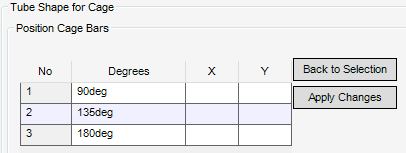
The Position Cage Bars part of the Create Rung Ladder Assembly window allows the administrator to position the vertical cage bars for the Rung Ladder Assembly.
|
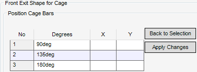
The Degrees column defines the rotation of the bar.
|
|
|
The X column defines the horizontal offset parallel to the rungs.
|
|
|
The Y column defines the horizontal offset perpendicular to the rungs.
|
Click Apply Changes to accept the changes made to the bar.
Click Back to Selection to discard any inputs and return to the Tube Shape for Cage part of the Create Rung Ladder Assembly window.
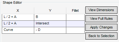
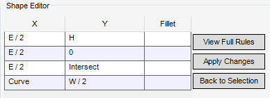
The Shape Editor part of the Create Rung Ladder Assembly window allows the administrator to specify the tube shape for the Rung Ladder Assembly.
|
The X column defines the horizontal offset parallel to the rungs.
|
|
|
The Y column defines the horizontal offset perpendicular to the rungs.
|
|
|
The Fillet column defines the radius of the fillet at the point.
|
|
|
The keyword Curve in the X column creates a curve centred on a point on the cage depth - half the cage width from the centre of the rungs with a radius given by the expression in the Y column. Two successive curves are not allowed.
|
|
|
The keyword Intersect in the X column creates a point at the intersection of the curve and a line at the offset given in the Y column.
The keyword Intersect in the Y column creates a point at the intersection of the curve and a line at the offset given in the X column.
The keyword Intersect must appear in a row directly before or directly after a line with the keyword Curve.
|
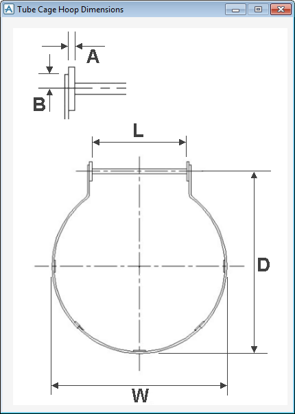
To visualise the dimensions of the shape, click View Dimensions to display the Tube Cage Hoop Dimensions window.
The administrator can view all Rules associated with the shape, click View Full Rules to display the Cage Tube Hoop Rules window.
Click Apply Changes to accept the changes made to the shape.
Click Back to Selection to discard any inputs and return to the Tube Shape for Cage part of the Create Rung Ladder Assembly window.
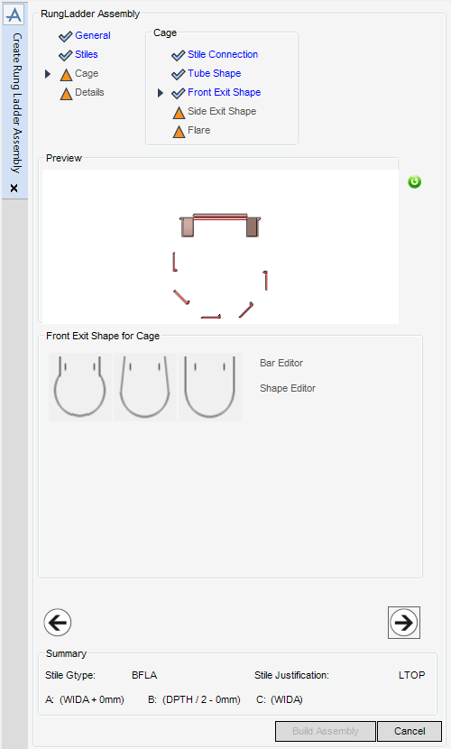
The Front Exit Shape for Cage part of the Create Rung Ladder Assembly window allows the administrator to select or define the front exit shape for the Rung Ladder Assembly.
The administrator can select a Front Exit Shape from the display. Alternatively, the administrator can modify a selected shape with the Bar Editor (refer to Front Exit Shape Bar Editor for further information) and the Shape Editor (refer to Front Exit Shape Editor for further information).
Click Next to display the Side Exit Shape for Cage part of the Create Rung Ladder Assembly window. Refer to Cage Side Exit Shape for further information.
The Position Cage Bars part of the Create Rung Ladder Assembly window allows the administrator to position the front exit vertical bars for the Rung Ladder Assembly.
The functionality available from the Front Exit Shape Bar Editor is identical to that available from the Tube Shape Bar Editor refer to Tube Shape Bar Editor for further information
The Shape Editor part of the Create Rung Ladder Assembly window allows the administrator to specify the front exit shape for the Rung Ladder Assembly.
The functionality available from the Front Exit Shape Editor is identical to that available from the Tube Shape Editor refer to Tube Shape Editor for further information
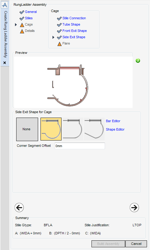
The Side Exit Shape for Cage part of the Create Rung Ladder Assembly window allows the administrator to select or define the side exit shape for the Rung Ladder Assembly.
The administrator can select a Side Exit Shape from the display. Alternatively, the administrator can modify a selected shape with the Bar Editor (refer to Side Exit Shape Bar Editor for further information) and the Shape Editor (refer to Side Exit Shape Editor for further information).
The corner segment is the L shaped part of the cage from the stile to the cage exit. Input a value in the field to define the Corner Segment Offset (the default is 0mm).
Click Next to display the Flare for Cage part of the Create Rung Ladder Assembly window. Refer to Cage Flare for further information.
Click Back to return to the Front Exit Shape for Cage part of the Create Rung Ladder Assembly window.
The Position Cage Bars part of the Create Rung Ladder Assembly window allows the administrator to position the side exit vertical bars for the Rung Ladder Assembly.
The functionality available from the Side Exit Shape Bar Editor is identical to that available from the Tube Shape Bar Editor refer to Tube Shape Bar Editor for further information
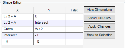
The Shape Editor part of the Create Rung Ladder Assembly window allows the administrator to specify the side exit shape for the Rung Ladder Assembly.
The functionality available from the Side Exit Shape Editor is identical to that available from the Tube Shape Editor refer to Tube Shape Editor for further information
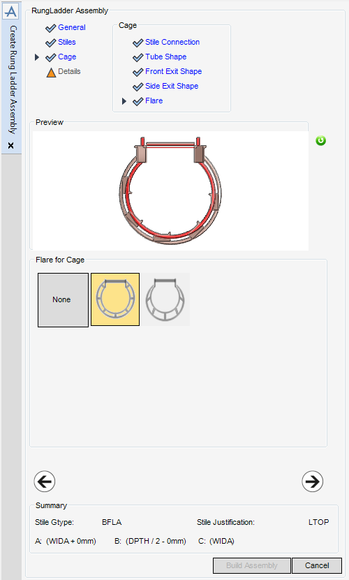
The Flare for Cage part of the Create Rung Ladder Assembly window allows the administrator to select the cage flare for the Rung Ladder Assembly.
|
•
|
None.
|
Click Next to display the Representation for Details part of the Create Rung Ladder Assembly window. Refer to Rung Ladder Details for further information.
Click Back to return to the Side Exit Shape for Cage part of the Create Rung Ladder Assembly window.
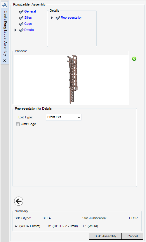
The Representation for Details part of the Create Rung Ladder Assembly window allows the administrator to preview the Rung Ladder Assembly in a number of different configurations.
Click Build Assembly to create the assembly.

