Structural Design
User Guide
Walls and Floors : Create Walls : Create Straight Wall
The Positioning Control window also displays, the positioning functionality available for selection is common throughout all design disciplines. Refer to Positioning Control for further information.
You are prompted to Define Straight wall start (Distance [0]) Snap:
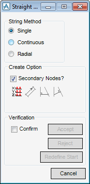
From the Straight Wall window there are three options available:
|
•
|
Single - Start and end points are individually defined for each section.
|
|
•
|
Continuous - Start point of subsequent walls is the end point of previous.
|
|
•
|
Radial - Start point for subsequent walls is the same as the first.
|
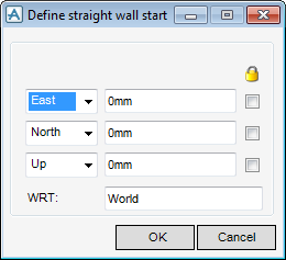
Click Define Start/End Explicitly to position the start of the wall explicitly by inputting explicit X, Y and Z co-ordinates. Refer to Define Vertex Explicitly for further information.
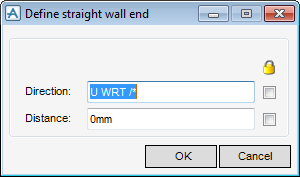
Click Define end a given distance and direction from start to position the end of the wall by specifying a distance and direction from the start of the wall. Refer to Define Vertex Offset from Previous for further information
Click Perpendicular from to create a wall perpendicular to the wall specified for the new wall start. You are prompted to Pick straight Section/Wall to derive perpendicular from:
Click Perpendicular to create a wall perpendicular to a selected wall. You are prompted to Pick straight Section/Wall to derive perpendicular end to:
If the Confirm check box in the Verification window is selected a line is drawn in the 3D view to indicate the position of the wall. Click Accept to draw the new wall or Reject to start again.
|
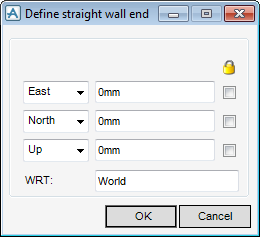
From the drop down menu, click to identify the direction of the East/West axis. The user can then input an explicit position value in the Position field.
|
|
|
From the drop down menu, click to identify the direction of the North/South axis. The user can then input an explicit position value in the Position field.
|
|
|
From the drop down menu, click to identify the direction of the Up/Down axis. The user can then input an explicit position value in the Position field.
|
If required, select one or all of the Lock check boxes to lock the explicit position of the current co-ordinate along the E/W, N/S or U/D axis.
In the WRT text box, input the name of the element to which all co-ordinates are interpreted with respect to, the default is World.
Click Apply to create the vertex or Cancel to discard any inputs and close the Define straight wall start/Define straight wall end window.
Input a value in the Direction field to define the direction of the vertex relative to the preceding vertex.
Input a value in the Distance field to define the distance of the vertex relative to the preceding vertex.
Click Apply to create the vertex or Cancel to discard any inputs and close the Define straight wall end window.


