Structural Design
User Guide
Walls and Floors : Walls and Floors Settings : Default Wall and Floor Specifications
|
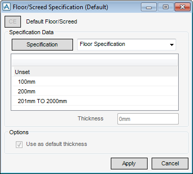
The check box is inactive for the Floor/Screed Specification (Default) window.
|
Click Apply to define the floor/screed specification default.
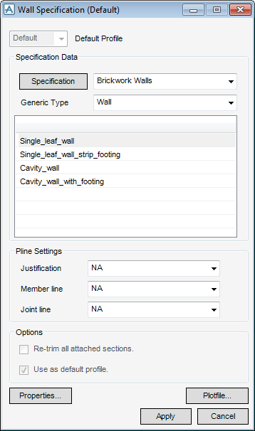
Use the Specification Data part of the Wall Specification (Default) window to select any of the specifications from the catalogue.
Click Specification to identify the current specification as the wall specification (default).
From the Generic Type drop-down list, select a standard from the list of available standards, once the selection has been carried out the Generic Type part of the window is automatically populated the generic types from the catalogue.
Use the Pline Settings part of the Wall Specification (Default) window to modify the Pline settings, by default the settings are set as NA (neutral axis) (normal choice of justification setting in practice is NA).
From the Justification drop-down list, select the justification from the available list, (justification determines the ‘Setting out’ position of the wall, that is the axis about which the geometry is offset).
From the Member line drop-down list, select the member line from the available list (determines how walls are shown in wireline views and drawings).
From the Joint Line drop-down list, select the joint line from the available list (determines the position of a joint relative to an attached section).
Use the checkboxes in the Options part of the Wall Specification (Default) window to re-trim all attached sections or use as the default profile.
Click Properties to display the properties of the profile.
Click Plotfile to display a graphical representation of the profile.
Click Apply to use these settings as the new default, the current specification is updated.

