Structural Design
User Guide
SDNF Export/Import
:
Technical Information
: SDNF - Structural Steel Detailing Neutral File Format
SDNF - Structural Steel Detailing Neutral File Format
All of the related Packets must be output at the same time. You cannot export a set of Linear Members and some time later another set.
Comments may be inserted anywhere through the file. They are indicated by the # symbol as the first non blank character.
Lines, apart from the Packet identifications, are free format delimited by spaces, up to a maximum length of 132 characters.
Text or character values are enclosed in double quotation marks, '"'.
Any '"' characters within such values are replaced with '.
The SDNF format is described as an ASCII file without further description of encodings or character sets. The SDNF interface attempts to transfer non-ASCII characters where appropriate, but warns if any characters with their 8
th
bit set are written to an SDNF file.
Export/Import different SDNF Formats
The interface can read SDNF files in both version 2 and version 3 of the format but write to only version 3.
Auto-detection of SDNF Formats
The system can automatically detect which version of the file you are inputting, you should need to do no more.
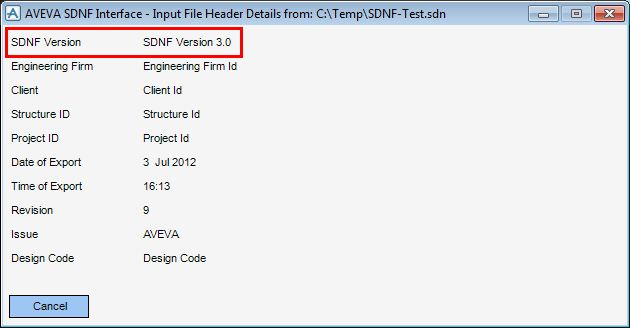
You can inspect the file header as before and an added line indicates which SDNF version it has found.
Packet 00 - Title Packet
Packet 00 is the SDNF file header. Only 1 Packet of this type must be included. It describes the run for the data transfer. Its record structure is:
repeat Record 11 as stated in Record 10
Note:
The Issue Code (Record 8) holds the Source Package of the SDNF file.
Packet 10 - Linear Members
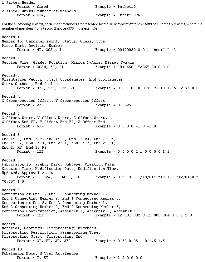
Straight Linear Members are the elements represented in Model by SCTNs and the straight segments of multi-segment GENSECs - straight prismatic profiles. They are described in the SDNF file.
There are several ways of defining a Linear Member using different combinations of the data elements, some of which are not interpretable by other systems. The method of interpretation of these fields is defined.
Location of Linear Members in Space
Close and rigorous study of the definition of Linear Members in SDNF reveals that there are many ways in which a Linear Member may be located in space. Combinations of information stored in records 3 to 5 per Linear Member determine the location. The main requirement is that the Cardinal Point is to be used to draw the lines in schematic drawings such that, where possible, a connected model may be deduced.
More generally, the interpretation is:
Record 4 is ignored completely - (2D X/Y offsets)
The Start and End cutbacks (Record 3) are ignored by default but can be enabled. Refer to
Linear Member Cutbacks
for further information.
The Start and End Position of the Member (Record 3) is the start and end position of the 'real length of steel' located on the line described by the Cardinal Point (Record 1).
The 3D Start and End Eccentricities (Record 5) then define the real start and end of the Cardinal Point 'Line' relative to the Node, if any. Thus, using Record 5 with Record 3, the Node position can be determined. AVEVA
SDNF would export this value, but does not do anything with it on import.
Note:
The sense of this eccentricity is a vector from the end of the member to the node position.
All packages are assumed to export the start and end positions of the Linear Member's Cardinal Point line.
Rotation and Orientation Vector
The Rotation and Orientation Vector attributes of a Linear Member determine the orientation of the element about its axis. The Orientation Vector defines the default orientation of the member before any rotation has been applied to it.
The Rotation is then taken as a right handed rotation about the axis from that default vector as one looks along the member from start to end - the local Z axis.
Packet 20 - Plates
Plates are represented in AVEVA E3Dâ„¢ by PANE elements as loops on the upper and lower faces.
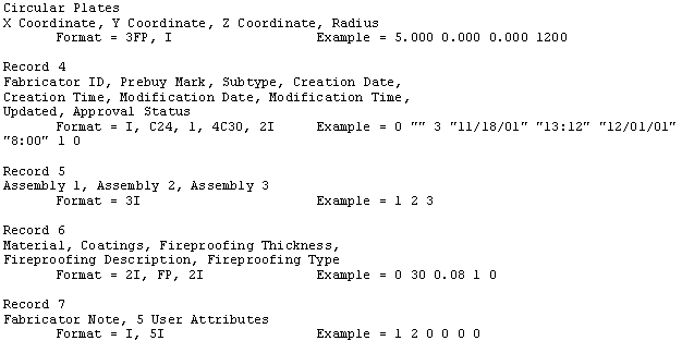
Each plate is represented by a variable number of records:
Plate periphery defines the type of boundary: 0 is a boundary with straight edges; 1 is a boundary with straight and curved segments; 2 is a circle. For both boundaries type 0 and 1, there are 2 loops of vertices, one for the plate top and the other for the plate bottom. For circular plates (type 2) there are 2 vertices representing the circle centre on the top and bottom faces.
Each set of vertex coordinates is followed by a flag that indicates whether the following boundary segment is straight or curved. In the case of the circular plate the "flag" is the circle radius.
The last vertex in the boundary, a duplicate of the first, has a connection flag of 0. Straight segments are indicated by the flag value of 1, curved segments by 2.
Rules of interpretation apply to the fields.
Order of Vertices
When exporting, the vertices describing a Plate are assumed to be defined in a manner according to the Right Hand Screw Rule, where the vertices are in a clockwise order when viewed along the normal to the Plate plane. For version 3 files, there is less of a requirement for the vertices to follow this rule as the interface can determine the plane normal from the separation between the loops.
When importing, the vertices may be defined in either direction.
Plate Origin
The Plate Origin is taken to be the position of the first vertex. This can cause confusion on import when the plate's origin has appeared to have changed. The more important thing is to see if the plate is in the same place.
Plate Orientation
The vector from the first vertex to the next vertex is taken as the local X axis. Knowing the fact that the plate is defined in a Right Hand Screw Rule manner, the plane normal can be determined, in turn determining the local Z axis. The Y axis then becomes the vector cross product of the Z and X axes.
Packet 22 - Holes
The geometric description of holes is very similar to that of their owning plates. Tests are made on import to verify that the hole does penetrate the owning plate. A hole completely penetrating the plate is translated into a secondary PLOO. Partially penetrating holes - depressions in the plate surface - are represented as NXTR elements.
Packet description
Each hole is represented by a variable number of records:
Sometimes, holes have been allocated to the wrong plate, this can be because the plates do not have a unique identifier.
Hole periphery defines the type of boundary: 0 is a boundary with straight edges; 1 is a boundary with straight and curved segments; 2 is a circle. For both boundaries type 0 and 1, there are 2 loops of vertices, one for the hole top and the other for the hole bottom. For circular holes (type 2) there are 2 vertices representing the circle centre on the top and bottom faces.
Each set of vertex coordinates is followed by a flag that indicates whether the following boundary segment is straight or curved. In the case of the circular hole the "flag" is the circle radius.
The last vertex in the boundary, a duplicate of the first, has a connection flag of 0. Straight segments are indicated by the flag value of 1, curved segments by 2.
Packet 30 - Member Loading
Loading of elements is not transferred by this interface.
No loads along the member are catered for.
Packet 40 - Connection Details
The Connection Details attached to one or each end of a Linear Member are described here. In design terms they are modelled by Primary or Secondary Joints. The mechanism by which the description text in record 3 is obtained is explained. Refer to
Location of Linear Members in Space
for further information. The record structure is:
The description is purely textual, no geometry is passed, for example, sniping.
Packet 50 - Grid Packet
Grid Packets are not transferred in this interface.
Packet 60 - Format Definition
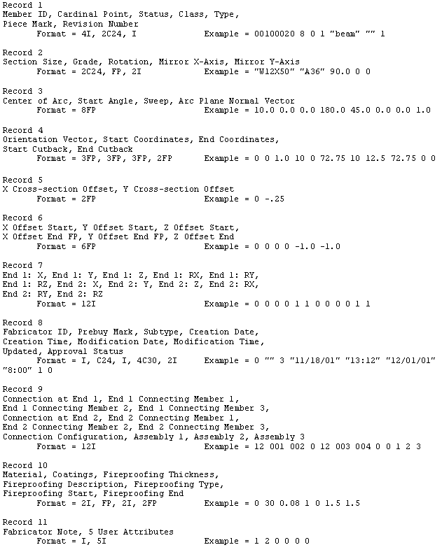
For the succeeding records, each arc member is represented by the 11 records, total of 11 times n records, where n is number of members from Record 2 (376 in the example).
1974 to current year.
AVEVA Solutions Limited and its subsidiaries. All rights reserved.