DRAW
User Guide
Add and Modify Drawing Objects : Modify Drawing Objects : Create Arrays of Objects
|
Note:
|
The objects from which the array is created can be selected before or after the Array window is opened. Refer to Select Objects for further information.
|
If one or more objects are selected before the Array window is opened, the array is created from them.
If objects are not selected before the Array window is opened, the OK button is greyed out and becomes active when one or more objects are selected.
To select objects, or to select different objects from those selected when the window was opened, click  in the Select objects part of the Array window.
The Array window is closed and you are prompted to Select objects
You are returned to the Array window.
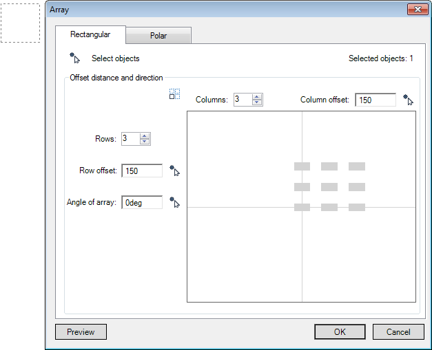
Select the Rectangular tab to create a Rectangular Array.
|
Alternatively, this can be specified on the drawing canvas. Refer to Specify Row Offset on Drawing Canvas for further information.
|
||
|
Click to display a preview of the array with the current settings. The Array window is closed and the preview displays on the drawing canvas.
|
Input values in the dimension fields and press Enter or click to identify the start point of the unit cell.
You are then prompted to select Other corner
Input values in the dimension fields and press Enter or click to identify the other corner of the unit cell.
The Array window displays, the Column offset and Row offset fields are populated with the identified offset distances, by default.
Click  next to the Column Offset field to specify the column offset distance on the drawing canvas.
Input a dimensional value in the field and press Enter to specify the distance between columns or click to identify the first point to specify the distance between columns.
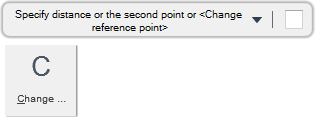
You are then prompted to Specify the second point or <Change reference point>
The Array window displays and the Column offset field is populated with the column offset distance, by default.
Throughout the column offset process you can press ESC to cancel the command. Additional functionality is also available.
|
Press the down arrow key and select Change reference point to modify the existing offset reference point.
|
|
Click  next to the Row Offset field to specify the row offset distance on the drawing canvas.
Input a dimensional value in the field and press Enter to specify the distance between rows or click to identify the first point to specify the distance between rows.
You are then prompted to Specify the second point or <Change reference point>
The Array window displays and the Row offset field is populated with the row offset distance, by default.
Throughout the row offset process you can press ESC to cancel the command. Additional functionality is also available.
|
Press the down arrow key and select Change reference point to modify the existing offset reference point.
|
|
Click  next to the Angle of array field to specify the angle of array on the drawing canvas.
Input an angular value in the field and press Enter to specify the array angle or click to identify the first point to specify the array angle.
You are then prompted to Specify the second point
The Array window displays and the Angle of array field is populated with the array angle, by default.
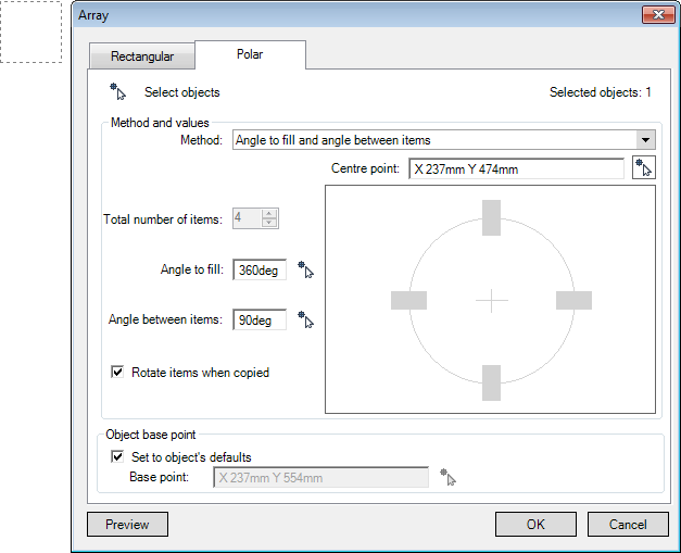
Select the Polar tab to create a Polar Array.
|
Alternatively, this can be specified on the drawing canvas. Refer to Specify Base Point on Drawing Canvas for further information.
|
|
|
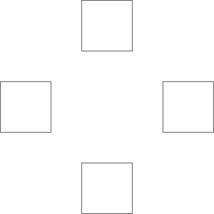
Click to display a preview of the array on the drawing canvas with the current settings. The Array window is closed.
|
Click  next to the Centre point field to specify the array centre point on the drawing canvas.
Input values in the dimension fields and press Enter or click to identify the centre point of the array.
The Array window displays and the Centre Point field is populated with the centre point coordinates, by default.
Click  next to the Angle to fill field to specify the angle to fill with array objects on the drawing canvas,.
The Array window is closed and you are prompted to Specify the second point (the first point is the previously defined centre point).
Input an angular value in the field and press Enter or click to identify the second point to specify the angle to fill.
The Array window displays and the Angle to fill field is populated with the angle to fill value, by default.
Click  next to the Angle between items field to specify the angle between array objects on the drawing canvas.
The Array window is closed and you are prompted to Specify second point (the first point is the previously defined centre point).
Input an angular value in the field and press Enter or click to identify the second point to specify the angle.
The Array window displays and the Angle between items field is populated with the angle value, by default.
Click  next to the Base point field to specify the base point coordinates to rotate objects around.
Input values in the dimension fields and press Enter or click to identify the base point.
The Array window displays and the Base point field is populated with the base point coordinates, by default.

