Schematic 3D Integrator
User Guide
Administration : Build and Compare Rules
Rules used by Integrator during Build and Compare operations can be configured. The following describes how to use the Integrator Project Configuration Explorer and explains the different types of configuration settings.
The default project configuration files can be modified using the Integrator Project Configuration Explorer. In the Integrator group, select Config to display the Integrator Project Configuration Explorer window. The Integrator Project Configuration Explorer will either be initially blank or will display the last set of modifications carried out.
|
To create a new configuration (empty or default), select File, then New. There are two options for new configuration files, refer to Empty Configuration or Default Configuration for further information.
|
|
|
An Empty Configuration file provides some simple default settings but will contain no rules for building and comparing elements.
|
|
|
A Default Configuration provides a copy of the out-of-the-box project configuration file containing a complete set of example rules that can be used out of the box but are available for customisation.
|
|
|
To open an existing configuration file, select File, then Open, from the displayed Open Project Configuration File window, select the ProjectConfiguration.xml file. By default the appropriate folder is displayed, defined as the Model Management folder under the folder indicated by the project defaults environment variable, for example: for the TTP project:
If required, use the project defaults environment variable to get quickly to the appropriate folder. For example, in the Open Project Configuration File window, for the TTP project, enter %ttpdflts%\ModelManagement in the Filename field and then press Enter.
|
|
|
To discard any changes made to the configuration file but keep it open, select File, then Revert to Saved.
|
|
|
To close the Integrator Project Configuration Explorer, select File then Close. If there are unsaved changes, a prompt is displayed save them.
|
|
•
|
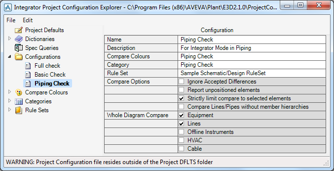
To add a new configuration, right click on Configurations in the Integrator Project Configuration Explorer and select Insert.
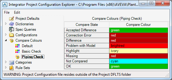
Compare Colours settings determines how different conditions are displayed in the 2D diagram and 3D views following a Compare action. One of the colours is also used as the Integrator highlight colour in the 3D view. Multiple sets of compare colours to be used with different configurations can be defined.
To add a new set of compare colours, right click on Compare Colours in the Integrator Project Configuration Explorer and select Insert.
Each Compare State can have a Compare Colour. To change the colour for that state, click on the colour box to the right of the state and select a colour from the browser.
The Compare States have the following meanings:
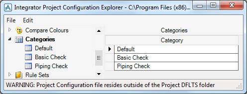
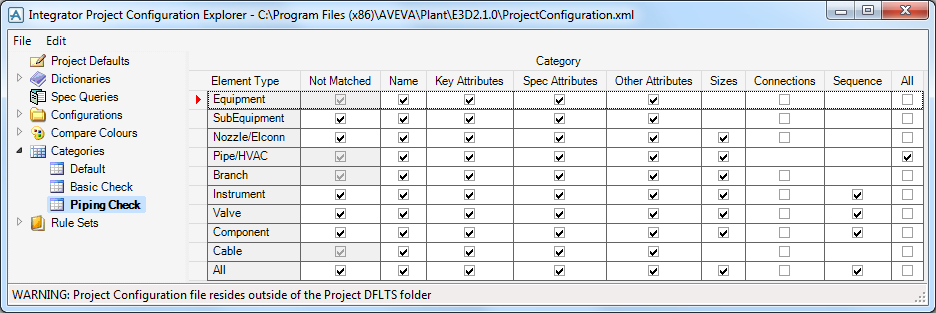
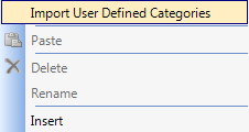
To add a new Category, right click Categories in the Integrator Project Configuration Explorer and select Insert.
During Compare operations the target will be an actual corresponding 3D object and during Build operations the target represents a "candidate" for a 3D object still to be created.
|
Create rules
|
|
|
Assign rules
|
A rule set holds all the rule groups for a particular pairing of database types. For example, the sample configuration has a default rule set for comparing Design database content against Schematic database content.
|
Note:
|
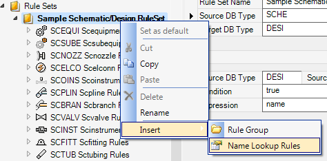
To add a new name lookup rule, right click in the Rule Set node in the model explorer or in the background of the Rule Set detail and select Insert > Name Lookup Rules.
Select Source DB Type, Source Element Type and Target DB Type from the respective drop down lists. Target Type Element is optional.
Condition must return a Boolean, for example:
Expression must return text for the Name of the Target Element, for example:
Rules will be applied if the Condition evaluates True and the Target Element Type matches (if specified). The keywords source and target which are used under Rule Groups (see below) are not available in Name Lookup Rules.
For Compare rules, the source and target elements can be referred to in the rule group condition. These can be used to refer to attributes or UDAs on the source or target using the "OF" syntax. For example, NAME of source refers to the NAME attribute of the source schematic object. User defined attributes can be used in the same way, for example, :MYATT of source. For Build rules, the target object does not exist and any reference to it may be undefined.
An extended notation allows access to attributes on related elements - owner, previous, next, for example, AREA of OWNER of OWNER of target.
The type expression must evaluate to a legal 3D database object type. This can be an explicit word, for example: EQUI, or a more complex expression calculated from schematic attribute settings. As in the rule group condition, the current source schematic object is referred to as source and its attributes are identified using the "OF" syntax, for example, GTYP of source. More powerful expressions can be created using the syntax described below.
In the situation where more than one 3D object type can be acceptable for comparison purposes, the Create type expression uses the special Variant function. This defines a list of all acceptable matching types, for example, Variant (TEE, OLET, FLAN). Each argument of the Variant function is an expression as defined above. When building, the first type listed in the Variant function will be used.
|
Note:
|
Quotes are not required in selector rules as Integrator will automatically include quotes for text selectors, for example: a rule with SCSTYP OF source operating on an SCVALV with SCSTYP PTFE-LINED will generate Choose with STYP |PTFE-LINED|.
|
The Integrator Project Configuration Explorer provides Intellisense feedback to assist with finding the appropriate entry as you edit a rule. Full syntax available can be displayed at the start of an entry by pressing the Alt and right arrow keys together. If a letter is entered, the available words starting with that letter are displayed.
|
•
|
Operators eq, ne, lt, le, gt, ge, test for equality, inequality, less than, less than or equals, greater than, greater than or equals, and apply to a pair of numerical expressions or a pair of alphanumeric expressions or a pair of Boolean expressions. (The result will be unpredictable if expressions of different type are compared.)
|
|
•
|
|
•
|
Operator not is used to negate the Boolean expression that follows it.
|
Attributes can generally be included in rules using the of syntax, for example: NAME of source, but the dot notation can also be used, for example: source.NAME. The dot notation is useful for array attributes, for example: source.BOREAR[3] < 100.
|
double Sine (double angle)
|
|
|
double Cosine (double angle)
|
|
|
double Tangent (double angle)
|
|
|
double Acosine (double value)
|
|
|
double Atangent (double value)
|
|
|
double Sqrt (double value)
|
|
|
double Log10 (double value)
|
|
|
double Logarithm (double value)
|
|
|
double Alog10 (double value)
|
|
|
double Alogarithm (double value)
|
|
|
double Absolute (double value)
|
|
|
integer Fix (double value)
|
|
|
integer Ceiling (double value)
|
|
|
integer Round (double value)
|
|
|
double Atant (double x, double y)
|
|
|
double Minimum (double a, double b, …)
|
|
|
double Maximum (double a, double b, …)
|
|
|
integer Length (string text)
|
|
|
integer Occurs (string text, string sub)
|
|
|
integer Instring (string text, string sub)
|
|
|
string Asstring (object value)
|
|
|
double Asreal (object value)
|
|
|
boolean Asboolean (object value)
|
|
|
string Substring (string text, integer start [, integer length])
|
|
|
string Left (string text, integer length)
|
|
|
string Right (string text, integer length)
|
|
|
string Before (string text, string sub)
|
|
|
string After (string text, string sub)
|
|
|
string Uppercase (string text)
|
|
|
string Lowercase (string text)
|
|
|
string Trim (string text)
|
|
|
string Lookup (string dictName, string key)
|
|
|
Integer Listposition
|
// the list order position of the current target element.
|
string Format (string pattern, object arg1, …)
The first argument is a pattern string into which the remaining arguments are substituted according to the format specifications included in the pattern string. This function follows the conventions defined for the .NET System.String.Format function.
This example generates a name from the values of three attributes on the source object. The first two values are straightforward substitutions. The third value is substituted as an integer value with a minimum of 3 digits, padded with leading zeros if necessary, for example: "45" -> "045".
The following examples illustrate some Rules under a particular Rule Group defined for schematic equipment.
Within this Rule Group there is one Create Action, this defines the type of object to be created during a Build operation, in this case EQUI. The Variant Count is 1, which means that the Compare operation will always check for an EQUI.
There are several Assign Actions. This one assigns a value to the attribute POS on the target object, taking that value from the POS attribute of the source object. The Build Action is set and the Compare Action is ignore. These options and their alternatives are described in more detail below.
The Assign Action has several properties:
|
An expression to generate the value for the target attribute, and can contain references to source. For build rules it should not contain references to target as this will be undefined at build time.
|
Build Action is the action carried out during a Build operation, allowable entries are:
Compare Action is the action carried out during a Compare operation, allowable entries are:
Mismatch Severity determines how a mismatch is reported during a Compare operation. Allowable entries are:
Mismatch Report is an optional text that will be output as a line in the compare report following the line on which the mismatch itself is reported.
Another Assign Action sets the attribute NAME to be the same in 3D as on the diagram.
|
Note:
|
Name rules based on target are not well supported in Integrator as target is undefined until it is actually created. In some cases it defaults to the source object for data if the target object is not available at that point. Consider an owner rule for building a ZONE when source is SCPLIN and target is the PIPE. It would seem reasonable to set the value of the ZONE name based on the SITE name plus a prefix, for example: ”format(‘{0}-{1}’, owner of owner of target, LNTP of source)”. But the ZONE is created before the target exists and so this rule will not give the desired result.
|
In the same block there are two further Assign Actions for NAME. The first of these has Assignee set to owner and contains an expression to define the name of the ZONE.
This next example illustrates a rule group for schematic valves. The source type shown below restricts this rule group to being applied where the source object is of type SCVALV.
This rule group has a number of nested rule groups. The first has a Condition that applies when the source object has a valid SPRE, denoted by being not equal to Nulref.
Here is the Condition:
This rule group has a Create Action that specifies the type of object to be created during a Build operation, in this case based on the attribute GTYPE of the source object.
The second nested rule group has a Condition that applies it when the source object does not have a valid SPRE, denoted by being equal to Nulref.
Here is the Condition:
This rule group has a further nested Rule Group that defines it as applying to source elements with particular GTYPE values.
This rule group also has a Create Action that specifies the type of object to be created during a Build operation, again based on the attribute GTYPE of the source object.
The Create Action has a Selector which will be used during a Build operation to select the object from the pipe specification. It will also be compared with a severity level of warning. Each Selector has a Question and Answer. This Selector takes the STYPE from the source object’s SCSTYP attribute.
This is accompanied by a Report Action that will output an error message in the Compare report if the flow direction is reversed.
A Report Action is used when the check required includes an expression based on 3D data, whereas an Assign Rule compares the whole value of a 3D attribute to an expression based on schematic data. The following example uses a Report Action to check a substring of a pipe name. In this example the PIPE name follows the convention Size-Fluid-Area-LineNumber and the SCPLIN name follows the convention Unit-Size-Fluid-Spec-LineNumber. To compare the Fluid requires a Report Action with Condition:
An appropriate Mismatch Report would be ‘Fluid code does not match’. If the condition evaluates false, then this message will be output in the report. Note that there is no output if it evaluates true.
Use the Integrator Project Configuration Explorer to add new rules and edit existing settings stored within the Project Configuration File.
To edit a section, click on its entry in the tree panel of the Configuration Explorer. Then click in the appropriate Value field in the grid panel and edit the entry.

