Schematic 3D Integrator
User Guide
Main Functions : Schematic and 3D Links
From a schematic element, when the Link option is selected, the Integrator searches for 3D elements that match according to the currently defined configuration rules. For example, for a schematic equipment, the Integrator looks for a corresponding 3D equipment element with a name or other attributes that complies with the rules. If a matching element that is not already linked is found, it is offered as the first in a list of candidates for linking, followed by unlinked non-matching elements.
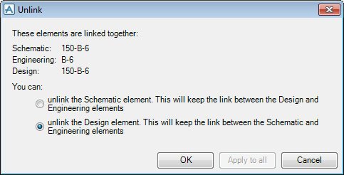
When the Unlink option is selected, a prompt may be displayed to select exactly which links are to be removed. For example, if schematic, design and engineering elements are all linked together, the schematic or just the design element can be selected, leaving the remaining link in place.
Integrator maintains its links as separate CYMLNK elements against which it can hold important information. Each CYMLNK object has attributes deslnk referencing the 3D model element, and schlnk referencing the schematic element. The CYMLNK element also holds a cmpstatus attribute to record its compare state. The 3D model and the schematic elements both have a cmplnk attribute referencing the CYMLNK object.
The CYMLNK elements are grouped in CYMGRP elements and exist in a single parent CYMWRL (link world) object. See Manage Links for available operations relating to link worlds.
|
Note:
|
CYMLNKs also have attribute englnk referencing engineering elements, but this is not used directly by Integrator.
|
To simplify navigation between corresponding schematic and 3D elements, Integrator provides the pseudo attributes schlnk and deslnk directly between these two elements. The pseudo attribute cmpsts returns the compare status description on the CYMLNK object or on any linked schematic or design elements, or on its linked ancestor. It is included by default in the Integrator Main Table.
Schematic elements have a Releaseto3dstatus attribute which should be set in the diagram authoring system. For example, AVEVA Diagrams provides a window to set this attribute. If the AVEVA Diagrams user then tries to modify a released object, they are prompted to confirm they do want to change it. If they do change it, the release status is unset P&ID Manager provides options to manage the release status of imported schematic data.
The syntax for the Releaseto3dstatus attribute in the Main Table column setup is RESTAT. When set it has the value 1. It can be set from the command line with RESTAT 1.
The Connection Details functionality is available for selection when a schematic equipment element is linked to a 3D equipment element or a E3D equipment element that is linked to a schematic equipment element.
The Equipment Connections window is populated with the nozzles and electrical connections on the schematic equipment, and the 3D equipment. The Link columns are populated with which connections are linked between the schematic and 3D model. The window is also populated with the piping and HVAC nozzles and electrical connections. It also lists connections that are direct to the equipment elements using the ECRFA and ELCXRF reference array attributes.
Use the Equipment Connections window, to change the specification reference of a nozzle, the Pipework Nozzle Specification or the HVAC Nozzle windows are displayed as appropriate. Or to create new nozzles or electrical connections and delete existing ones.
To change which 3D connection is linked to a particular schematic connection, select the schematic connection in the Schematic Equipment list, select the 3D connection in the 3D Equipment list, then select Set Link.
For the 3D connection between branch and equipment, a nozzle must be selected, but the Integrator cannot determine which nozzle, since there is no schematic nozzle to link with. Use the Pick Connection window to enable the selection or creation of a nozzle accordingly.
The Pick Connection window is populated with the 3D branches that have unresolved connections. When a branch is selected in the Unresolved Branches list, the following actions are carried out by Integrator:
The Connection columns are also populated with which branches are connected to which nozzles.
Use the Pick Connection window to change the specification reference of a nozzle, select the nozzle in the Connections list, then click Modify Specification. The Pipework Nozzle Specification or the HVAC Nozzle windows are displayed, as appropriate. Or create new nozzles and delete existing ones.
To change which unresolved branch is connected to which nozzle, select the branch in the Unresolved Branches list, select the nozzle in the Connections list, then select Set Connection. The selected branch will be connected to the selected nozzle.
Integrator can automatically link all matched elements from an Integrator Report, from the main menu bar, click Edit > Link all matched elements.
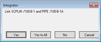
Individual links can be selected or skipped. Alternatively all matches can be linked, click Yes to All to automatically link all matches. On completion, the report indicates newly linked elements in cyan and any failed or skipped links in red.
A log of the linking actions is displayed in the Command Line window.
Integrator can automatically update attributes on matched or linked elements from an Integrator Report. From the main menu bar, click on Edit > Copy All to 3D.
A log of the updating actions is displayed in the Command Line window.
The Integrator Report window supports a drag and drop function from the Diagram Viewer or Design Explorer. The Integrator Report window has a drop site for linking, at the base of the Integrator Report window.
An element can be dragged from the Diagram Viewer, Design Explorer, or from the Integrator Report, and dropped in the drop site. If dragged from the Integrator Report, the action must start on either the schematic element cell or the 3D element cell to determine which element is to be dragged. A subsequent drop onto the drop site will either replace the element selected for linking, or offer to link to it, depending on the relative types.
In the Main Table or Diagram Viewer select the elements to link or unlink, then right click, from the displayed menu, select Link or Unlink.
As previously stated, when Link is selected the Integrator searches for design or schematic elements that match according to the currently defined configuration rules and populates a window with the results. Thus enabling verification of consistency of 3D model against the schematic. Refer to Schematic and 3D Links for further information.
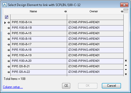
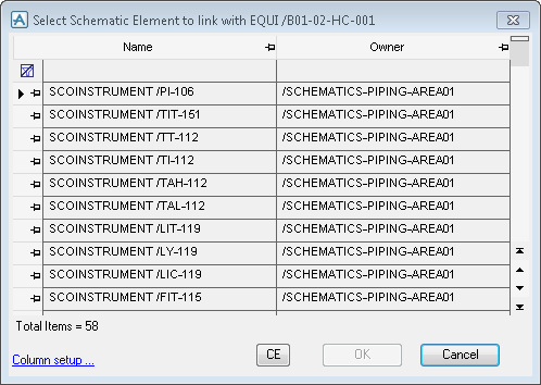
Which window is displayed is dependent upon where the elements is selected from, design elements are selected from the Diagram Viewer (Select Design Element to link to) and schematic elements are selected from the Schematic 3D Integrator Main Table (Select Schematic Element to link to). Refer to Design Elements or Schematic Elements for further information.
Use the Select Design Element to link with XXXX window to select an element to link to.
For a description of the functionality available from Column setup, refer to Set Columns in the Search Results for further information.
Use the Select Schematic Element to link with XXXX window to select a schematic element to link to.
For a description of the functionality available from Column setup, refer to Set Columns in the Search Results for further information.
To unlink a element, select the element from the main object table, then select Unlink. An Unlink window is displayed.
To initiate the Link or Unlink functionality from the Command Line window, refer to Use Integrator from the Command Line for further information.


