Piping
Assembly Manager
A pipe assembly is a series of components and branches which are replica copies (in all aspects) of original components and branches. Or an assembly definition may be created to access existing macros or forms. Pipe assemblies are also used in Pipe Splitting, refer to Pipe Splitting for further information.
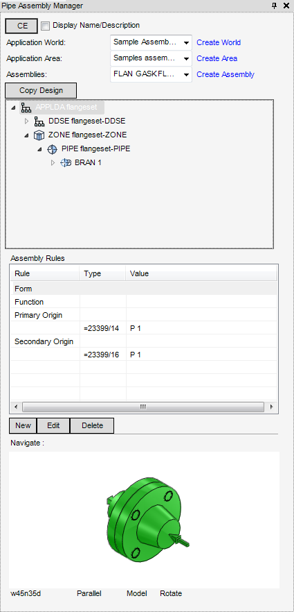
All the tasks performed that are associated with creating or modifying pipe assemblies are initiated from the Pipe Assembly Manager window, the window acts as a task hub.
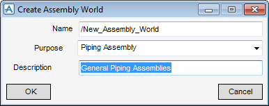
Use the Create Assembly World window to create an Assembly World element in the database hierarchy.
Input the attributes for the assembly world element, click OK to create the assembly world element or click Cancel to discard any inputs and close the Create Assembly World window.
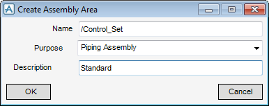
Use the Create Assembly Area window to create an assembly area element in the database hierarchy.
Input the attributes for the assembly world element, click OK to create the assembly world element or click Cancel to discard any inputs and close the Create Assembly Area window.
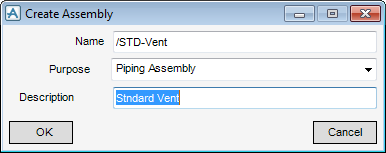
Use the Create Assembly Area window to create an assembly element in the database hierarchy.
Input the attributes for the assembly world element, click OK to create the assembly world element or click Cancel to discard any inputs and close the Create Assembly window.
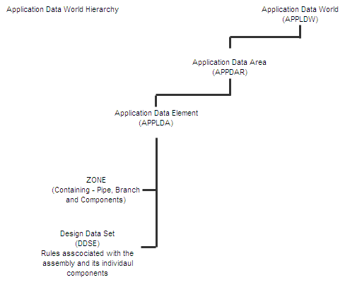
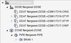
The basic hierarchy has now been created is displayed in the Model Explorer and the Pipe Assembly Manager window which can now be populated with assemblies. The easiest way to create an assembly is to copy an existing assembly already created in the design, click Copy Design. The assembly displays in the Model Explorer and the Pipe Assembly Manager window.
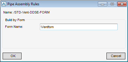
Use the Pipe Assembly Rules window to create a form rule.
In the Form Name field, enter the name of the form to display when the assembly is used, the form name must not contain !! or ().
Click OK, the Form Name is added to the Assembly Rules and stored in the Assembly Design Data Set so that it can be run each time the assembly is used.
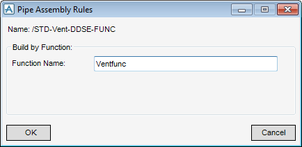
Use the Pipe Assembly Rules window to create a func rule.
In the Function Name field, enter the name of the function to be performed when the assembly is used, the function must not contain !! or ().
Click OK, the Function Name is added to the Assembly Rules and stored in the Assembly Design Data Set so that it can be run each time the assembly is used.
|
Note:
|
Secondary origins are used in pipe splitting to derive correct spool lengths, refer to Spooling for further information.
|
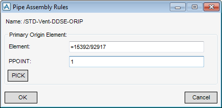
Use the Pipe Assembly Rules window to set a primary origin.
To edit or delete any form, function or primary and secondary origin, from the Assembly Rules part of the Pipe Assembly Manager window, click Edit or Delete.
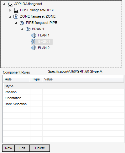
The addition of rules enables the default actions to be supplemented or overridden, refer to Component Rules for further information.
Use the Assembly Rules part of the Pipe Assembly window, to create addition rules or edit existing component rules, select the component to populate the Component Rules pane.
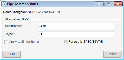
Use the Pipe Assembly Rules window to create a new STYPE rule or edit an existing one.
|
Note:
|
The new or edited Stype rule overwrites the default Stype.
|
The name of the Design Data Set is named, in the Alternative STYPE part of the Pipe Assembly Rules window. Input or amend the Specification and Stype.
Click to select Apply to Similar Items check box to apply all similar items in the assembly.
Click to select Force this SPEC/STYPE check box forces the assembly to use a particular specification and stype regardless of the pipe specification where the assembly is being built.
Click OK to create or edit the Stype rule and close the Pipe Assembly Rules window or Cancel to discard any inputs and close the Pipe Assembly Rules window.
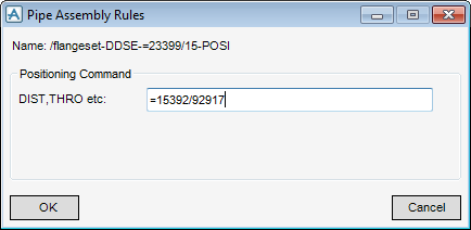
Use the Pipe Assembly Rules window to create a new positioning command or edit an existing one.
The new or edited Positioning command overwrites the default Position.
The name of the Design Data Set is named, in the Positioning Command part of the Pipe Assembly Rules window. Input the Positioning Command.
Click OK to create or edit the Position rule and close the Pipe Assembly Rules window or Cancel to discard any inputs and close the Pipe Assembly Rules window.
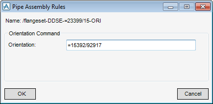
Use the Pipe Assembly Rules window to create a new Orientation Command or edit an existing one.
The name of the Design Data Set is named, in the Orientation Command part of the Pipe Assembly Rules window. Input the Orientation Command.
Click OK to create or edit the Orientation rule and close the Pipe Assembly Rules window or Cancel to discard any inputs and close the Pipe Assembly Rules window.
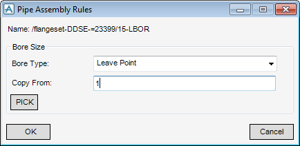
Use the Pipe Assembly Rules window to create a new Bore Selection rule or edit an existing one.
The new or edited Bore Selection rule overwrites the default bore selection.
The name of the Design Data Set is named, in the Bore Size part of the Pipe Assembly Rules window. From the Bore Type drop-down list, select the bore type to act as a reference.
In the Copy From field, identify the location of the existing assembly.
Select PICK, to select the component to act as a reference.
Click OK to create or edit the Bore Size rule and close the Pipe Assembly Rules window or Cancel to discard any inputs and close the Pipe Assembly Rules window.
To set a Key Element, right-click the component in the design hierarchy of the Pipe Assembly Manager window to display the Key Element drop-down menu.
Select Set Key Element from the drop-down list to display the key element in the design database.
To remove a Key Element, right-click the component in the design hierarchy of the Pipe Assembly Manager window to display the Key Element drop-down menu.
Select Remove Key Element from the drop-down list, the key element is removed from the design database.

