Piping
Pipe Fabrication : Spooling and Checks
|
•
|
|
•
|
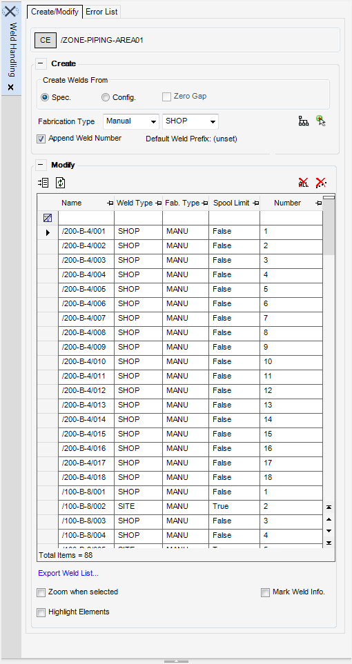
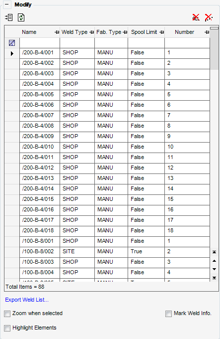
Use the Weld Handling window to create, modify, and delete welds in the currently selected spool. Also use the window, to view welds which could not be created.
Click CE to identify the currently selected element as the working element. Use the Create part of the Weld Handling window to create and define a weld.
|
Select Spec to create a weld from the current pipe spec. The weld thickness is pre-defined by the spec.
|
||
|
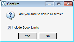
By default the Include Spool Limits check box is selected, allowing you to Include Spool Limits within the deletion.
|
|
|
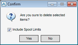
By default the Include Spool Limits check box is selected, allowing you to Include Spool Limits within the deletion.
|
|
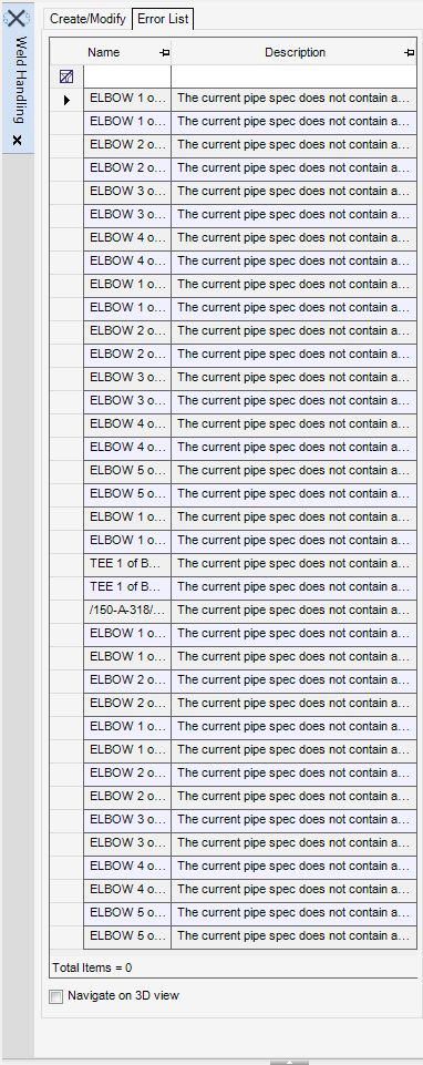
When welds cannot be created between components, the name and description of the error populates the Error tab of the Weld Handling window.
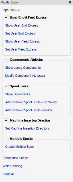
Use the Modify Spool window to define pipe end & feed excess, loose components, spool limits, machine insertion direction and create multiple spools.
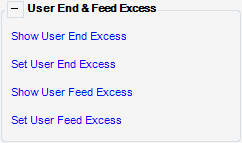
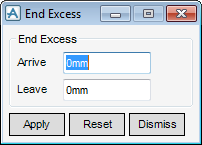
Use the User End & Feed Excess part of the Modify Spool window to display and modify the end and feed excess values.
Use the Component Attributes part of the Modify Spool window to display and modify the component attributes.
|
Click to display the Component Attributes window. Refer to Modify Component Attributes for further information.
|
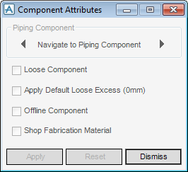
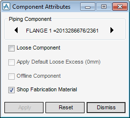
Use the Component Attributes window to define the attributes for piping components.
|
The check box becomes active when the user selects the Loose Component check box, the Offline Component check box must be left unchecked and the component must be positioned at the end of a spool.
|
|
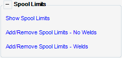
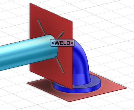
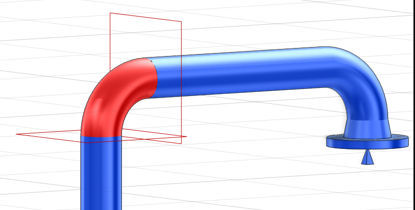
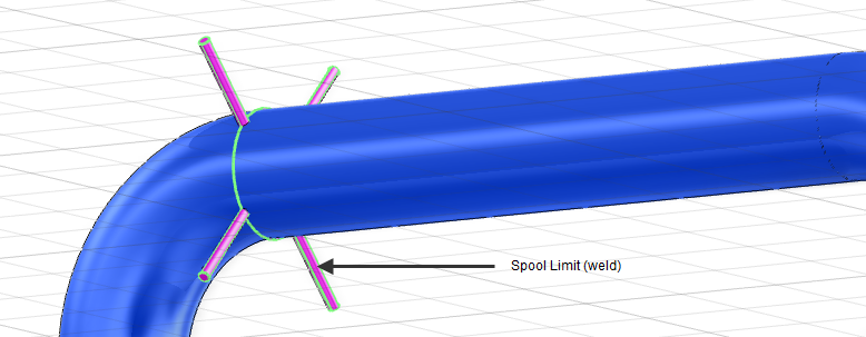
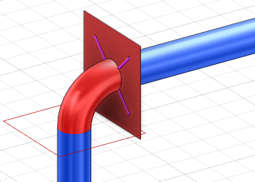
Use the Spool Limits part of the Modify Spool window to display and modify the spool limits. A spool limit can be added or deleted. The spool limit is created with a field WELD component.
|
Pick first component or <ESC> to finish : on the 3D graphical view
|
|
|
If the Add/Remove Spool Limits - No Welds is selected the weld is not displayed on the 3D graphical view.
|
|
|
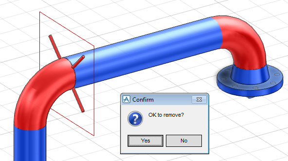
Pick first component or <ESC> to finish : on the 3D graphical view
|
|
|
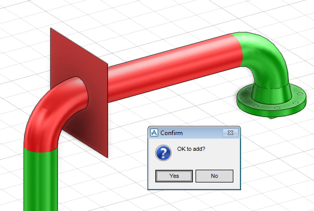
Pick a second component, a Confirm window is displayed asking OK to remove, click Yes to remove the spool limit.
|
|
|
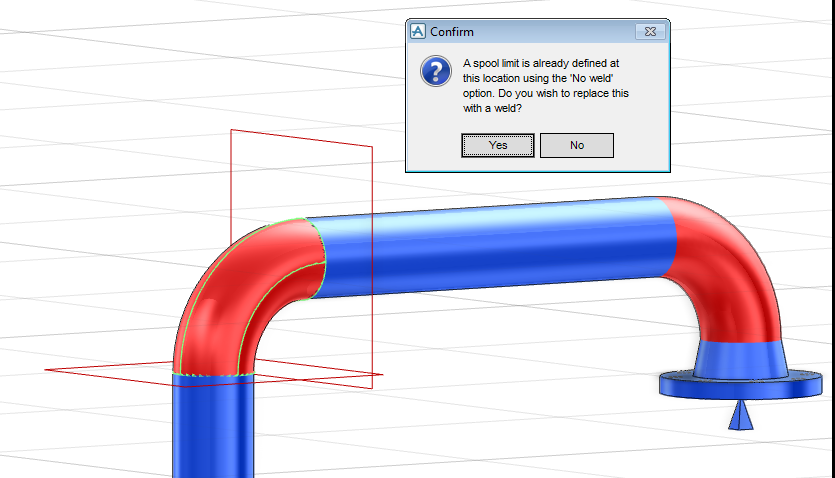
If the spool limit location on the currently selected pipe already has a spool limit created without a field WELD component and Add/Remove Spool Limit - Welds is selected, the following Confirm window is displayed:
|
|
|
Click Yes to replace the spool limit - without a weld component with a weld.
|
Use the Set Machine Insertion Direction part of the Modify Spool window to define the bending direction for the spool.
|
Select the radio button and specify the Arrive to define the spool arrive end as the machine insertion direction.
|
|
|
Select the radio button and specify the Leave to define the spool leave end as the machine insertion direction.
|
|
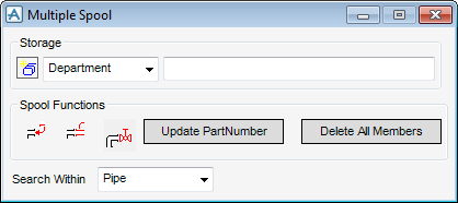
Use the Create Multiple Spool part of the Modify Spool window to define a Spool Drawing (SPLDRG) element.
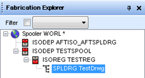
The Fabrication Explorer is automatically displayed, SPLDRG elements can be viewed in the Fabrication Explorer.
Use the Modify Spool window to create a multiple spool.
|
Select from the drop-down list to create a Department element. Enter a Department Name in the field to the right of the drop-down list, the element displays in the Fabrication Explorer.
|
|
|
Select from the drop-down list to create a Registry element. Enter a Registry Name in the field to the right of the drop-down list, the element displays in the Fabrication Explorer.
|
|
|
Select from the drop-down list to create a Spool Drawing element. Enter a Spool Drawing Name in the field to the right of the drop-down list, the element displays in the Fabrication Explorer.
|
|
Use the bottom part of the Modify Spool window to define the links with Fabrication Checks and Weld Handling. Functionality is also available to clear all Aid Texts on the 3D graphical view.
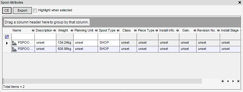
Use the Spool Attributes window to modify the spool name and other attributes. Functionality is also available to add a new attribute column to the list of available columns.
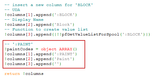
Add new columns using the ppGetColumnsForSpool.pmlfnc file, located in the pmlfnc folder. The following example describes how to add a new attribute column, called Paint, to the list of spool attributes.
Open the ppGetColumnsForSpool.pmlfnc file, the highlighted text in the example below displays the text required to be added to the file.
Reload the Spool Attributes window to the application using the Command Window, enter pml reload form !!pfSpoolAttributes.
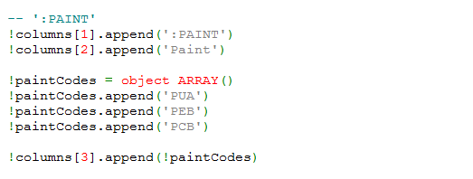
Add new drop-down value list using the ppGetColumnsForSpool.pmlfnc file, located in the pmlfnc folder. The following example describes how to add a value list to the Paint attribute column.
Open the ppGetColumnsForSpool.pmlfnc file, the text in the example below displays the text required to be added to the file.
Reload the Spool Attributes window to the application using the Command Window, enter pml reload form !!pfSpoolAttributes.
Alternatively, add a new drop-down value list using the ppGetColumnsForSpool.pmlfnc and pfGetValueListForSpool.pmlfnc files.
Open the ppGetColumnsForSpool.pmlfnc file, the highlighted text in the example below displays the text required to be added to the file.
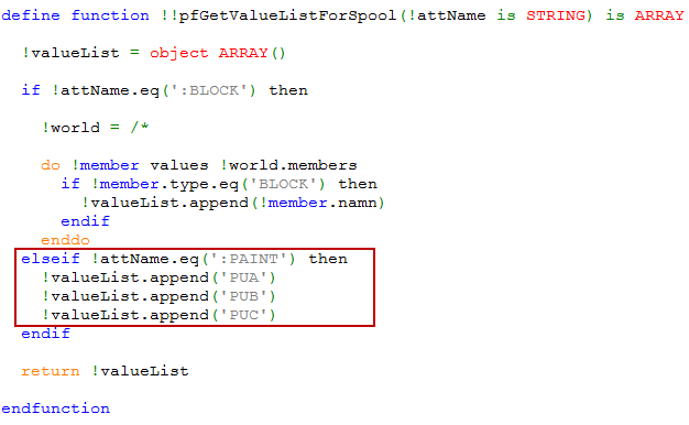
Open the pfGetValueListForSpool.pmlfnc file, the highlighted text in the example below displays the text required to be added to the file.
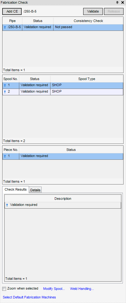
Use the Fabrication Check window to check pipe models for production readiness. Make sure a SITE or ZONE element is selected as the CE in the design hierarchy.
|
Click to display the Default Fabrication Machines part Fabrication Check window. Refer to Default Fabrication Machines for further information.
|
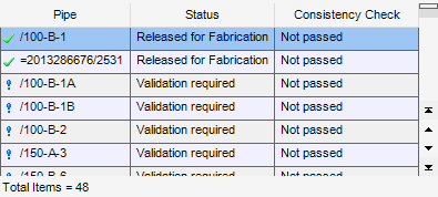
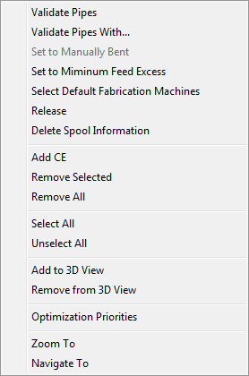
Right-click on the Pipe part of the Fabrication Check window to display a pop-up menu of available options associated with the selection.
|
Use the Select Fabrication Machines window to view the default bending machines available for selection.
|
|
|
Selects the default fabrication machines to be used instead of the fabrication machines specified by BendMacReference in fabrication checks. Refer to Default Fabrication Machines for further information.
|
|
|
Generates spool and piece elements for the currently selected pipes, the status is set to Ready for fabrication regardless of outstanding warnings.
|
|
|
Displays the Optimization Priorities window, use it to order the optimisation priorities for the fabrication check. The modified priorities are temporary and is invalid after closing the Fabrication Check window. The functionality of the Optimization Priorities window is explained as part of the process for defining Optimisation Criteria for Bending and Welding. Refer to Optimization Criteria for Bending and Welding for further information.
|
|
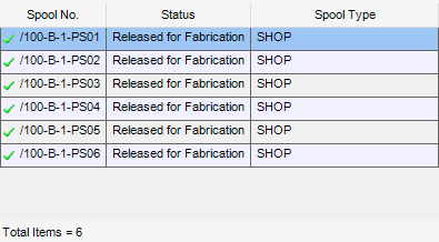
Use the Spool part of the Fabrication Check window, to view the list of pipe spools contained within the CE, together with the fabrication status and spool type.
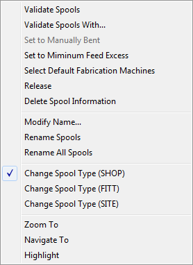
Right-click on the Spool part of the Fabrication Check window to display a pop-up menu of available options associated with the selection.
|
Use the Select Fabrication Machines window to view the default fabrication machines available for selection.
|
|
|
Selects the default fabrication machines to be used instead of the fabrication machines specified by BendMacReference in fabrication checks.
Refer to Default Fabrication Machines for further information.
|
|
|
Generates spool and piece elements for the currently selected spools, sets the status to Ready for fabrication regardless of outstanding warnings.
|
|
Use the Piece No. part of the Fabrication Check window to view the list of pipe pieces contained within the CE, together with the fabrication status.
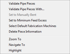
Right-click on the Piece No. part of the Fabrication Check window to display a pop-up menu of available options associated with the selection.
|
Use the Select Fabrication Machines window to view a list of available fabrication machines for selection.
|
|
|
Selects the default fabrication machines to be used instead of the fabrication machines specified by BendMacReference in fabrication checks. Refer to Default Fabrication Machines for further information.
|
|
The Check Results tab displays a description of the Fabrication Check errors, the check results display are classified as:
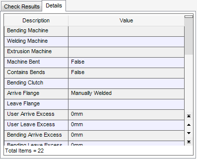
The Details tab displays all values from the fabrication check, the values are stored in PPIECE elements.
When the default fabrication machines are selected, the fabrication checks only use these default fabrication machines, instead of using the BendMacReference attribute of the zone, pipe and branch.
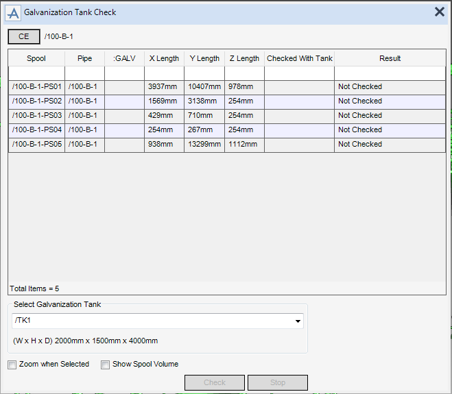
Use the Galvanization Tank Check window to check the validity of a galvanisation tank against a pipe spool.

