Piping
Pipe Fabrication : Modelling
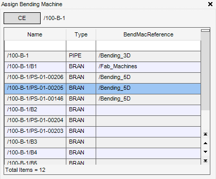
Whenever a pipe is created, the BendMacReference attribute is populated with the default value assigned to the piping specification. By default, the BendMacReference attribute is assigned with a valid default bending machine reference from the pipe specification.
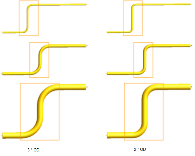
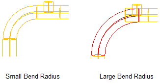
If a pipe bend Radius is too large and needs to be changed to a smaller bend radius for design reasons, then the BendMacReference attribute for the zone, pipe or branch can be modified to point to another Fabrication Machine World (FMWL), Group (FMGRP) or Machine (FMBEND).
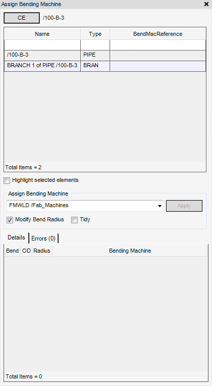
Click CE to identify the currently selected SITE, ZONE, PIPE or BRAN as the currently selected element.
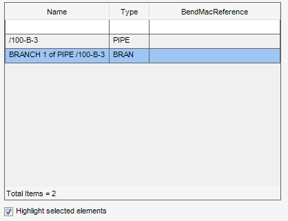
Select the Highlight selected elements check box to highlight the selected table item in the 3D graphical view.
The Assign Bending Machine part of the Assign Bending Machine window allows the user to assign a new bending machine and modify the bend radius of the selected element.
|
Select an FMWLD, FMGRP or FMBEND from the drop-down list to assign a BendMacReference attribute value to the selected element.
|
|
|
Select the check box to tidy the BendMacReference attribute value of the selected element by default. Refer to Tidy BendMacReference Element for further information.
|
Click Apply to assign a new BendMacReference modify the bend radius of the selected element.
If the Modify Bend radius check box is selected, the bend radius of the selected element is modified by default.
If the Tidy check box is selected, the BendMacReference attribute value of the selected element is tidied by default. If the BendMacReference attribute value of a branch is the same value as the owning pipe, the attribute value is removed from the branch.
The example below shows a pipe and branch with a duplicate BendMacReference attribute value.
When the Tidy check box is selected, the BendMacReference attribute value is removed from the branch.
The Details tab displays a list of change details for the pipework structure, calculated when the bending machine is assigned.
The Errors tab displays a list of errors for the pipework structure, calculated when the bending machine is assigned.
|
•
|
BendMacReference is not defined.
|
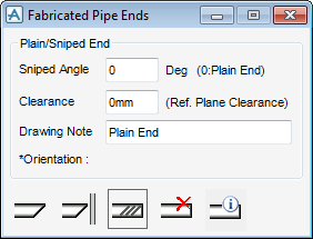
The Fabricated Pipe Ends window defines a plain, slanted or threaded pipe end.
|
If required, enter a statement in the Drawing Note field, the default is Plain End, the note is displayed on the drawing.
Click Create Sniped Ends, select a pipe end in the 3D graphical view.
The prompt ‘Pick pipe end:’ is displayed.
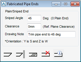
Specify the angle for the Sniped End and display a Drawing Note.
|
||||
|
Enter a value (greater than 0) in the Slanted Angle field to define the angle of the Slanted End in degrees.
If required, enter a statement in the Drawing Note field, the default is Trim pipe end to {deg}, the note is displayed on the drawing.
Click Create Sniped Ends. The user must select a pipe end in the 3D graphical view.
The prompt ‘Pick pipe end:’ is displayed.
|
||||
|
Enter a value (greater than 0) in the Sniped Angle field to define the angle of the Sniped End in degrees.
Enter a dimensional value in the Clearance field to define the reference plane clearance.
Click Create Sniped Ends with Reference Plane.
|
||||
|
Click Create Threaded End. The user must select a pipe end in the 3D graphical view.
The prompt ‘Pick pipe end:’ is displayed.
Select a Threaded Type from the Thread Type drop-down list.
The user can configure the Thread Type, refer to Threaded Ends for further information.
|
||||
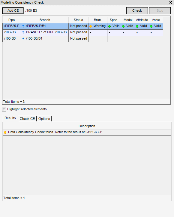
To add pipes to be checked, in the Model Explorer click to select the required pipe. Then select Add CE, the CE is displayed in the Modelling Consistency Check window.
To highlight the pipe to be checked in the 3D graphical view, click to select the Highlight selected elements check box. By default the check box is not selected.
To run modelling consistency checks, click Check, a short description (pass or fail) of the check is displayed on the Results tab.
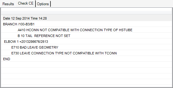
On the CE tab, a more detailed description of the modelling consistency checks are displayed.
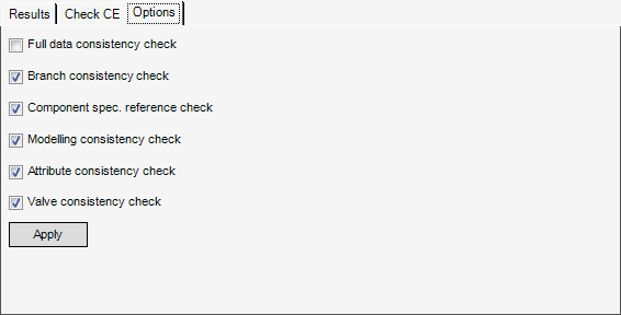
On the Options tab, all of the modelling consistency checks are displayed, by default all the checks are selected.



.png)
.png)
