Supports
Customisation Guide
Framework Template Administration
:
Project Special Templates
: Filter and Build Settings at an HVAC Project Special Template
Filter and Build Settings at an HVAC Project Special Template
HVAC project special templates allow frameworks to be built with limited automated re-sizing for variable size ducting.
HVAC Structure Template
The list of HVAC templates, for the HVAC STRT element to be supported, is filtered on the settings of two uda’s. They are :MdsHv (described in
Filter Settings at a Piping or Tray Project Special Template
) and :MdsRange and are both attributes of the STRU template.
The second filter control, :MdsRange, is implemented for HVAC templates only. It controls whether insulation exists on the HVAC STRT element being supported. The settings are shown in the table below:
Setting
Action
0
Restricts the STRU template to support only HVAC STRT elements that are uninsulated.
1
Restricts the STRU template to support only HVAC STRT elements that are insulated.
2, any other value, or left unset
Allows the STRU template to support HVAC STRT elements that are either uninsulated or insulated.
Having set the udas at the STRU templates, consider also :MdsCheck. Set this uda at the time the template is selected and/or built from the list displayed in the Select Project Special Template window. The options are shown in the table below:
Setting
Action
true
Includes the insulation thickness of the HVAC STRT element in the design and build calculations of the STRU template members copied to the current HVAC Special Support.
false
(default setting)
Exclude the insulation thickness of the HVAC STRT element in the design and build calculations of the STRU template members copied to the current HVAC Special Support.
HVAC Structure Template Members
Like a standard framework template, HVAC special template members are added to the template relative to the origin of the template STRU.
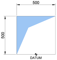
Each of the HVAC Project Special Support templates are built on a base HVAC STRT duct sized 500mm wide x 500mm high. This is done to enable relative sizing and positioning of template members when the HVAC special template is built on a different duct size.
When the template is built, new elements are created and positioned as required for each support case.
It is possible to create GENSECS (representing framework bars), SUBS (representing items, for example, end plates) and EXTR (extrusions which can be used to represent, for example, linings).
It is possible to control the relative positions of the GENSEC, SUBS and EXTR element types (including the vertices of EXTR elements when they are applied to a duct of different size to a reference duct 500mm x 500mm. It is also possible to control the relative extension of GENSEC elements.
The control of element relative positioning and extension is controlled by the UDAs:
:MdsConfigA
- standard UDA to be used for element positioning and GENSEC extension in a single axis
:MdsConfigB
- Additional options to enable relative positioning in a second axis.
Both UDAs are configured as a series of character delimited instructions, a typical instruction string is:
:MDSConfigA true,U,1,HEIGHT\true,0.5\true,0.5
The instruction string can be broken down into three sections (delimited by the '\' character).
Element Positioning
Enable Relative Element Positioning
Move Direction
Proportion of difference from Reference Duct
HVAC Relative Dimension
Description
Field to control whether or not relative positioning is enabled for the current element.
An E3D model direction wrt the owning STRU. If positioning is required, any positive offsets are performed in this direction.
Distance proportion of the calculated difference between the reference HVAC duct and the supported HVAC in the model that will be used to offset the current element. For example, if a 300mm x 300mm HVAC is being supported, the difference is 300mm - 500mm = -200mm and bar positions will need to move to suit the smaller duct.
The cross-sectional dimension to be used to calculate any dimension differences between the reference HVAC and the current element.
Example
TRUE
W
0.5
WIDTH
GENSEC START / GENSEC END Extension
Enable START/END Extension
Proportion of difference from Reference Duct
Description
Field to control whether or not an extension change is enabled for the current element for the START or END of the GENSEC.
Distance proportion of the calculated difference between the reference HVAC duct and the HVAC being supported in the model that is used to offset the current element. For example, if a 300mm x 300mm HVAC is supported, the difference is 300mm - 500mm = -200mm and bar positions will need to move to suit the smaller duct.
Example
TRUE
0.5
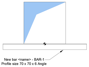
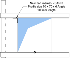
Example: Add a Support Bar at the Datum
When adding a framework bar to the template, note that the bar must be named with the convention <template STRU name> -BAR- <incremented bar number>
The :MDSConfigA UDA is set as:
:MDSConfigA false,,,\true,0.5\true,0.5
Element Positioning
Enable Relative Element Positioning
Move Direction
Proportion of difference from Reference Duct
HVAC Relative Dimension
Value
FALSE
Description
No relative positioning required.
No value required.
No value required.
No value required.
GENSEC START Extension
Enable START extension
Proportion of difference from Reference Duct
Value
TRUE
0.5
Description
GENSEC start extension is required.
Bar start is extended by 0.5 x (500 - HVAC width).
GENSEC END Extension
Enable END extension
Proportion of difference from reference duct
Value
TRUE
0.5
Description
GENSEC end extension is required.
Bar end is extended by 0.5 x (500 - HVAC width).
The overview of the setup for the bar is that no relative position change is required when the bar is created as the bar is always the same position relative to the datum. However, the start and end of the bar must be extended relative to the width of the duct that the framework is created against.
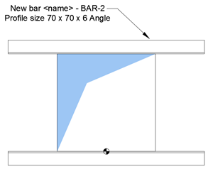
Example: Add a Bar above the HVAC
In this case, relative positioning of the bar must be enabled as it is affected by any height changes to the duct. GENSEC start and end extensions are the same as bar 1.
The configuration is:
:MDSConfigA true,U,1,HEIGHT\true,0.5\true,0.5
Element Positioning
Enable Relative Element Positioning
Move Direction
Proportion of difference from Reference Duct
HVAC Relative Dimension
Value
TRUE
U
1
HEIGHT
Description
Relative positioning required.
Offsets are in the UP direction, relative to STRU orientation.
Bar is offset by 1 x (500 - HVAC dimension in relative direction, for example, HEIGHT).
The HVAC dimension that is compared against the reference.
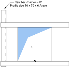
Example: Add a Vertical Bar to the Framework
When adding a vertical bar to the template, note that the vertical bar must be named with the convention <template STRU name> -V<incremented bar number>. In this case, relative positioning of the vertical bar must be enabled as it is affected by any width changes to the duct. Relative extension of the GENSEC end is required but no extension of the START is required.
The configuration is:
:MDSConfigA true,W,0.5,WIDTH\false,\true,1
Element Positioning
Enable Relative Element Positioning
Move Direction
Proportion of difference from Reference Duct
HVAC Relative Dimension
Value
TRUE
W
0.5
WIDTH
Description
Relative positioning required.
Offsets are in the WEST direction, relative to STRU orientation.
Bar is offset by 0.5 x (500 - HVAC dimension in relative direction, for example, WIDTH).
The HVAC dimension that is compared against the reference.
GENSEC END Extension
Enable END Extension
Proportion of difference from Reference Duct
Value
TRUE
1
Description
GENSEC end extension is required.
Bar end is extended by 1 x (500 - HVAC height).
Example: Add a Guide Bar to the Framework
The bar requires relative positioning changes to two axes where both height and width differences occur. Both the :MDSConfigA and :MDSConfigB UDAs are used. :MDSConfigA controls the width positioning of the bar and :MDSConfigB controls the height positioning. No bar extension changes are required in this case.
The configuration is:
:MDSConfigA true,W,0.5,WIDTH\false,\false,
:MDSConfigB true,U,1,HEIGHT\false,\false,
Element Positioning :MDSConfigA
Enable Relative Element Positioning
Move Direction
Proportion of difference from Reference Duct
HVAC Relative Dimension
Value
TRUE
W
0.5
WIDTH
Description
Relative positioning required.
Offsets are in the WEST direction, relative to STRU orientation.
Bar is offset by 0.5 x (500 - HVAC dimension in relative direction, for example, WIDTH).
The HVAC dimension that is compared against the reference.
Element Positioning :MDSConfigB
Enable Relative Element Positioning
Move Direction
Proportion of difference from reference duct
HVAC Relative dimension
Value
TRUE
U
1
HEIGHT
Description
Relative positioning required.
Offsets are in the UP direction relative to STRU orientation.
Bar is offset by 1 x (500 - HVAC dimension in relative direction, for example, HEIGHT).
The HVAC dimension that is compared against the reference.
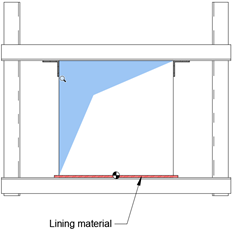
Example: Add a Lining to the Framework
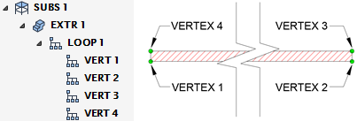
The lining is built from the following element hierarchy.
Note:
Additional bars have been added and BAR 1 has been shifted down to allow for the liner thickness. These processes are not documented in this example.
It is possible to apply relative position changes to the SUBS, EXTR and VERT elements in the hierarchy. There is no need to consider changes occurring as a result of height difference because the liner is located under the datum of the duct being supported. Differences in width must be accounted for. Each vertex of the liner must be configured to move relative to any difference in width. Vertexes 1 and 4 must respond to width changes in the west direction and vertexes 2 and 3 must move in the east direction.
Element Positioning: Vertex 1 and Vertex 4
The configuration is:
:MDSConfigA true,W,0.5,WIDTH\false,\false,
Enable Relative Element Positioning
Move Direction
Proportion of difference from Reference Duct
HVAC Relative Dimension
Value
TRUE
W
0.5
WIDTH
Description
Relative positioning required.
Offsets are in the WEST direction, relative to STRU orientation.
Bar is offset by 0.5 x (500 - HVAC dimension in relative direction, for example, WIDTH).
The HVAC dimension that is compared against the reference.
Element Positioning: Vertex 2 and Vertex 3
The configuration is:
:MDSConfigA true,E,0.5,WIDTH\false,\false,
Enable Relative Element Positioning
Move Direction
Proportion of difference from Reference Duct
HVAC Relative dimension
Value
TRUE
E
0.5
WIDTH
Description
Relative positioning required.
Offsets are in the EAST direction, relative to STRU orientation.
Bar is offset by 0.5 x (500 - HVAC dimension in relative direction, for example, WIDTH).
The HVAC dimension that is compared against the reference.
1974 to current year.
AVEVA Solutions Limited and its subsidiaries. All rights reserved.