ISODRAFT
User Guide
Piping Components in ISODRAFT : In-line Components, Including Straight-through Valves
|
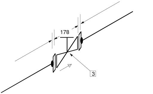
Figure 6:1.
|
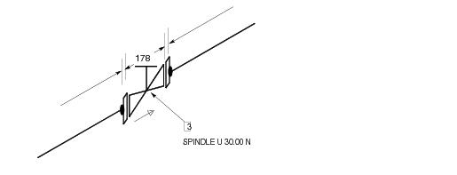
The directions of Valve operating spindles are correctly indicated. Valve operating spindles that are skewed will be plotted in the nearest primary direction and a comment giving the actual direction added, as shown in Figure 6:2.: Valve with flow arrow and direction text for spindle.
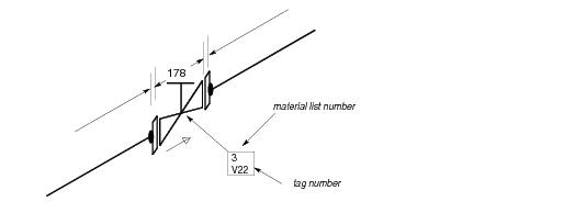
If Valve tag numbers have been stored in the DESIGN database as names, they can be included in the boxed enclosures below the material list numbers if they are switched on using the TAGGING command. See Figure 6:3.: Valve with tag number.
|
Figure 6:3.
|


