ISODRAFT
User Guide
Bolting
: Example Wafer Lug Valve
Example Wafer Lug Valve
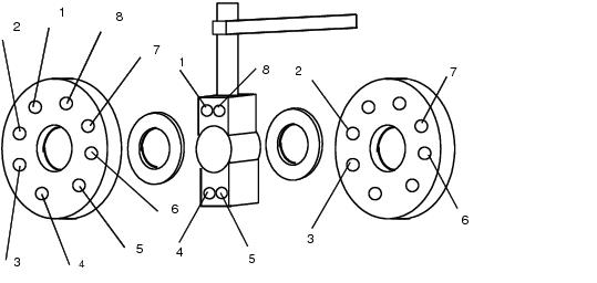
The diagram below illustrates the wafer lug valve scenario. This example shows a wafer valve requiring a set of 12 bolts. There are:
•
4 machine bolts which pass through the whole joint from one flange to the other (Numbers 2, 3, 6, 7).
•
4 cap screws on each side of the valve, which secure the valve to the flanges (Numbers 1, 4, 5, 8).
The machine bolt lengths are based on the combined thickness of the two flanges, both gaskets, and the valve itself. The cap screw lengths are based on the thickness of a single flange and gasket combined with the tapping depth in the valve body.
Figure 4:3.
Example Wafer Lug Valve
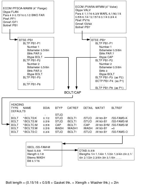
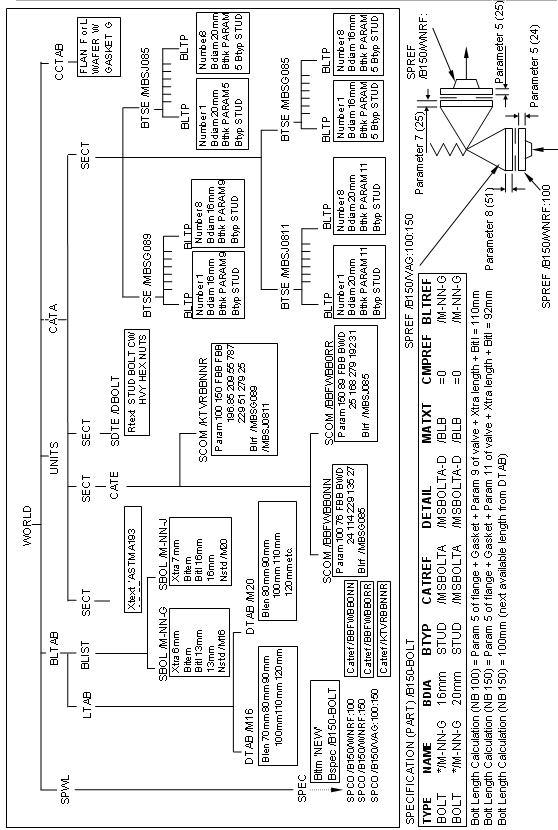
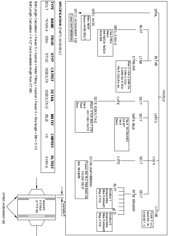
A data flow diagram for the bolting of a typical lug valve is shown in
Figure 4:4.: Example Data Flow Diagram for a Wafer Lug Valve
Figure 4:4.
Example Data Flow Diagram for a Wafer Lug Valve
1974 to current year.
AVEVA Solutions Limited and its subsidiaries. All rights reserved.