ISODRAFT
User Guide
Symbol Keys
: Pipe Components with More Than Four Connections
Pipe Components with More Than Four Connections
PCOMs and SHUs may be shown with up to six off-line legs. Flanges and filters can be shown with a single off-line leg. Off-line legs may be regarded as tapping points positioned on the piping component; for example, instrument connections on orifice flanges, vents in valve bodies, etc.
SKEYs FOWN (Weld-neck orifice flange), FOSO (Slip-on orifice flange) and FI** (Inline filter) have automatic tee points. Any other symbols requiring off-line legs must be user-defined.
The links between the 2D symbol representation and the 3D component model are provided by Tee points. A maximum of six tee points may be defined for each symbol. They can be defined in any order, but must be distributed on the fitting as shown:
The following rules for tee point layout must be obeyed:
•
No tee points may be positioned on the X axis
•
No more than 3 tee points may be positioned above the X axis
•
No more than 3 tee points may be positioned below the X axis
•
No more than 2 tee points may be positioned on the Y axis
•
No more than 2 tee points may be positioned to the left of the Y axis
•
No more than 2 tee points may be positioned to the right of the Y axis
A symbol which has no tee points defined, but which is modelled with fitting taps, will have them drawn from P0.
A symbol which is symmetrical should have tee points defined symmetrically about the symbol axis. This allows any tee leg orientation to find an available tee connection point when detailing takes place. For example, for a circular flange the user should allow at least three tee points, even though only one may be needed. ISODRAFT will decide from the tapping point and the symbol definition which tee point should be used.
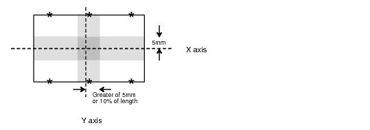
The default tee point is at the P0 of the symbol. The tee points defined on the X and Y axes will be used if the coordinates given fall on, or within a specified distance of, these axes. Other tee points will be used if the coordinates fall outside the following tolerances:
•
The outer tee points in the direction of the Y axis will be used if the coordinates are further along the Y axis than 5mm
•
The outer tee points in the direction of the X axis will be used if the coordinates are further along the X axis than 5mm
or
10% of the true length (whichever is the greater)
Thus, in the following diagram, coordinates in the shaded areas will select the tee points in the shaded areas and coordinates in the unshaded areas will select tee points in the unshaded area:
In the case of an offset fitting, the centreline is taken to be the line joining the start point to the end point of the symbol. To simplify the generation of tee points on both the X and Y axes, the value of -1 may be used for the XPOS and YPOS in the symbol definition for tee point coordinates. (Note that PCOM and SHU symbols cannot be ‘flipped’.)
ISODRAFT incorporates facilities for setting the scale of the tapping leg and for switching tapping leg dimensions and/or coordinates on and off. See the TAPPING command.
1974 to current year.
AVEVA Solutions Limited and its subsidiaries. All rights reserved.