ISODRAFT
User Guide
Isometric Drawing
: Origins of Coordinate Axes
Origins of Coordinate Axes
By default, all spatial coordinates on isometrics are given in the World coordinate system. The AXES command allows the user to specify a different coordinate system for the isometric. The user can use the origin of any database element which has an origin.
Each owning element (Site, Zone etc.) in a design project has its own coordinate system for locating the elements it owns. The coordinates of an element are usually defined with respect to its owner, and these coordinates are
not
normally the same as World coordinates.
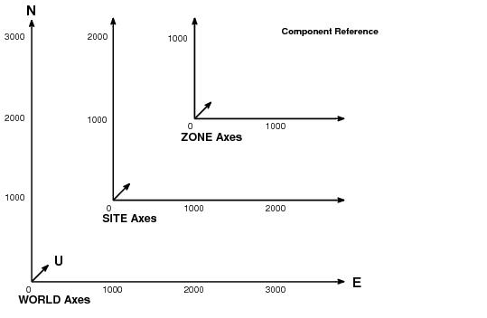
Figure 9:1.
Coordinate systems within a design project
With reference to
Figure 9:1.: Coordinate systems within a design project
, the E/W and N/S coordinates of the piping component are:
E3000
N3000
with respect to the World axes
E2000
N2000
with respect to the Site axes
E1000
N1000
with respect to the Zone axes.
Figure 9:1.: Coordinate systems within a design project
illustrates this in two dimensions, but the same principle applies to the elevation axis.
Spatial coordinates are shown on the drawing, by default, at all pipe termination or connection points. The user can control when coordinates are plotted by using the COORDINATES command. The user can choose to switch off coordinates of end points which are connected to Nozzles, continued on other Pipes or which have connection type Open, Clos, Vent or Dran.
1974 to current year.
AVEVA Solutions Limited and its subsidiaries. All rights reserved.