HVAC
HVAC Main Branch
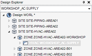
An HVAC Main Branch is a starting point or branch head to which all other HVAC Component elements can be added. Referring to the Hierarchy, an HVAC Main Branch below an existing HVAC System element must be created. For a detailed explanation of how to create an HVAC System element refer to HVAC System Element.
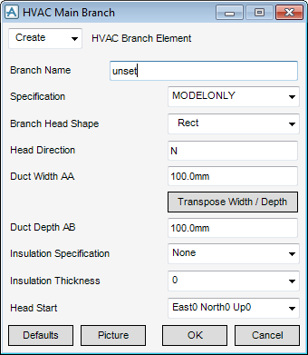
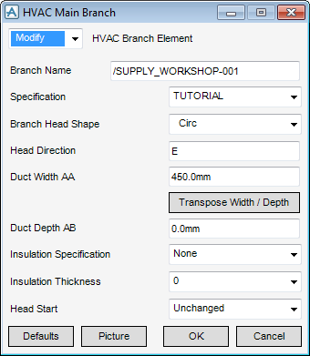
Select HVAC / Branches in the Categories drop-down list and then select Main Branch Element in the Available Type drop-down list to display the HVAC Main Branch window:
The HVAC Main Branch window is a dual purpose window, use it to either Create a new HVAC Main Branch element (by default) or Modify an existing HVAC Main Branch element.
To create a HVAC Main Branch make sure Create is selected in the drop-down list in the top left of the HVAC Main Branch window.
In the Branch Name box, input the name of the new HVAC Main Branch element.
By default the specification selected in Default Detailing Specification will be used but an alternative specification from the Specification drop-down list for individual HVAC Branches can be selected.
|
Note:
|
All HVAC Components later created below the branch will use the Specification selected in this drop-down list. To use different specifications within a ductwork run, a new branch must be created at each point a different specification is used.
|
The Branch Head Shape specifies the cross-section shape of the HVAC that will be connected to the branch head.
In the Branch Head Shape drop-down list select from either Rect (Rectangle), Circ (Circle) or Oval.
After selecting a Branch Head Shape click Picture to display a detailed drawing of the Branch shape. Refer to Main Branch, the detailed drawing is clearly labelled, these labels correspond to dimensions that must be input in the following input fields:
Valid dimensions for Head Direction are E (East), N (North), U (Up), -E (negative East), -N (negative North) or -U (Negative Up).
In Duct Width AA (AA is an abbreviation for Arrive A Dimension) enter the width of the Branch Head.
In Duct depth AB (AB is an abbreviation for Arrive B Dimension) enter the depth of the Branch Head.
Select an insulation thickness from the Insulation Thickness list. The available options will change depending on the Insulation Spec selected. If no insulation is required, select 0mm.
By default only one Insulation Specification is available, if a new insulation specification is required, refer to the system administrator.
The way that the starting coordinates of the Branch Head are derived can be changed by selecting from a choice of options in the Head Start drop-down list:
|
•
|
East0 North0 Up0 - (default) positions the branch head at the co-ordinates 0,0,0 (origin).
|
|
•
|
Head of ID Branch - Position the Branch Head at the Head of an existing Branch. A prompt to click in the 3D View at the position of the existing Branch Head is displayed.
|
|
•
|
Tail of ID Branch - Position the Branch Head at the Tail of an existing Branch. A prompt to click in the 3D View at the position of the existing Branch Tail is displayed.
|
|
•
|
ID Nozzle - Position the Branch Head at the end of an existing Nozzle element. A prompt to click in the 3D View at the position of the existing Nozzle is displayed.
|
|
•
|
ID Ceiling Fitting - Position the Branch Head at the end of an existing Ceiling element. A prompt in the 3D View to Identify HVACFI is displayed.
|
|
•
|
Cursor - A prompt to click anywhere in the 3D View is displayed. This will be used as the position for the new Branch Head.
|
|
•
|
ID Design Point - Position the Branch Head at the position of a P-point of an existing element. A prompt to click in the 3D View on the P-point of an element is displayed.
|
|
•
|
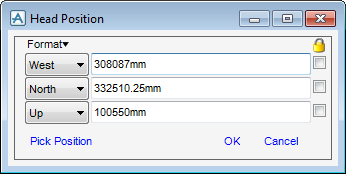
Explicit - Display the Head Position window, enter values in the text fields or click Pick Position to make a graphical pick.
|
|
•
|
Unchanged - The position of the Branch Head remains unchanged. The option is only applicable in Modify mode. If used in Create mode the position defaults to the origin.
|
Click Defaults to reset all dimensions in the HVAC Main Branch window to out of the box (initial) dimensions.
Click Picture to display a detailed drawing of the HVAC Main Branch. The labels used in the detailed drawing match the labels used in the input fields of the HVAC Main Branch window.
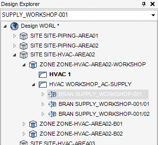
Click OK to create a new HVAC Main Branch element in the Design database and close the HVAC Main Branch Window. You will be returned to the HVAC Window.
To modify a existing HVAC Main Branch element first select an existing HVAC Main Branch element in the Model Explorer.
Using the HVAC Window select HVAC/Branches in the Categories pull-down and select Main Branch Element in the Available Type drop-down list, to display the HVAC Main Branch window.
The HVAC Main Branch window will be populated with the attributes of the currently selected HVAC Main Branch element.
Type in new attribute dimensions for the HVAC Main Branch element or reset the attributes to the Defaults and then click OK to commit the change.

