HVAC
Components : Inline Plant Equipment : Circular Fire Damper
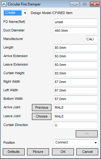
Select Inline Plant Equipment in the Categories drop-down list and then CIRCULAR, Fire Damper in the Available Type drop-down list to display the Circular Fire Damper window:
|
•
|
To visualise how the dimensions equate to the actual piece of HVAC, click Picture to display a detailed drawing for Circular Fire Damper.
|
Note:
|
The fields will be pre-populated with default dimensions. These dimensions are governed by the details defined in the HVAC Catalogue. The Manufacturer cannot be changed.
|
Specify a type of joint to use for the Arrjoint (Arrive Joint) and Leajoint (Leave joint). Refer to Create/Modify HVAC Component for a detailed description.
After selecting the type of joint to use for the Arrive Joint and Leave Joint you must enter the Curtain Direction.
In the Curtain Direction specify the axis that should be used. Valid axes are E (East), N (North), U (Up), -E (negative East), -N (negative North) or -U (Negative Up).
|
•
|
|
•
|
Click Unchanged (default when Modify is selected) - positions the component at the co-ordinates 0.00.
|
|
Note:
|
Unchanged is usually used, when Modify is selected, it does not connect the component but positions it at 0.00, in effect in a floating position.
|
Click Fit to orientate the Circular Fire Damper to automatically match the outlet (p-leave) of the previous piece of HVAC to the inlet (p-arrive) of the next piece.
Click OK to create the Circular Fire Damper component and close the Circular Fire Damper Window. You will be returned to the HVAC Window.

