Equipment
Equipment : Import/Export DGN : Import DGN
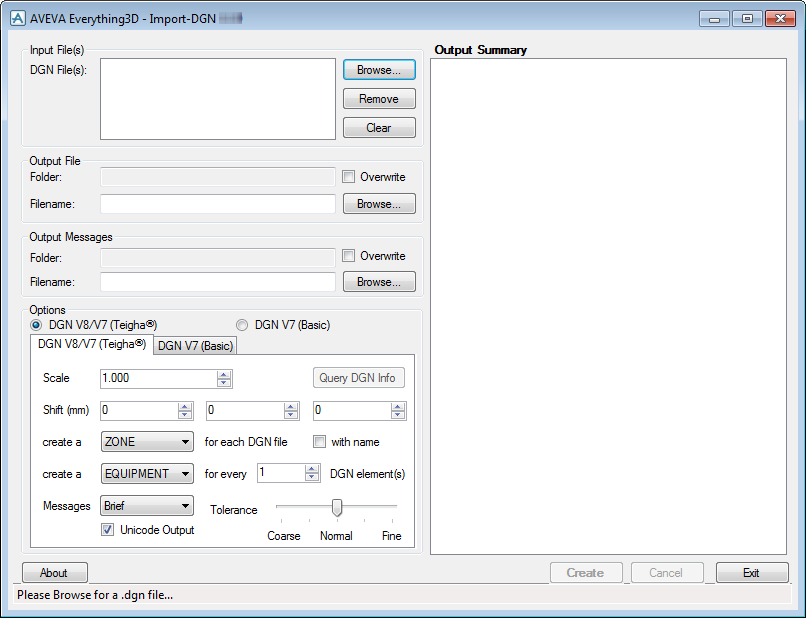
Use the AVEVA Everything3D - Import-DGN window to:
All the options for ImPlant - I2.exe are supplied as command-line arguments. Refer to Scripting Import-DGN (Teigha® facilities) for further information.
The Import-DGN (Basic facilities) functionality can be run from the windows command line, or from a script such as a Windows .bat file, a perl program, from PML using the SYSCOM command, use the ImPlant - I.exe program from the main AVEVA E3D™ executables folder. Refer to Scripting Import-DGN (Basic facilities) for further information.
There are some cases where the translation of MicroStation geometry differs between Basic facilities and Teigha® facilities. The Teigha® facilities do a more complete job but can translate somewhat fewer types of geometry into standard primitives. For example, some elements recognised as extrusions by Basic facilities may be translated as a facetted polyhedron in Teigha® facilities. However, it does translate others to a more compact and faster representation. Refer to Limitations, Warnings and Errors for further information.
Some dgn files are structured with a highly nested cell structure, with very few top-level elements. Import-DGN uses the top-level elements to help structure the model in the Design macro, so if a large model is composed of a very few cells with complex contents, it is best to use the MicroStation Drop tool (using the drop complex option) to drop these until the top-level elements are no more complex than the user wants to put into a single subequipment or substructure element in Design.
The current release of Import-DGN cannot translate some MicroStation Feature Solids. The MicroStation Solid Utilities: Convert to Solid tool can be used to convert these to Smart Solids.
Some dgn files are structured with a highly nested cell structure, with very few top-level elements. Import-DGN uses the top-level elements to help structure the model in the Design macro, so if a large model is composed of a very few cells with complex contents, it is best to use the MicroStation Drop Element tool (using the drop complex option) to drop these until the top-level elements are no more complex than the user wants to put into a single subequipment or substructure element in Design.
Import-DGN (Basic) cannot translate MicroStation Smart Solids, the MicroStation Drop Element tool can be used to drop all Solids to Surfaces.
Import-DGN (Basic) cannot translate some MicroStation Feature Solids. The MicroStation Solid Utilities: Convert to Solid tool can be used to convert these to Smart Solids, and follow the instructions above.
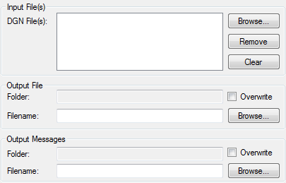
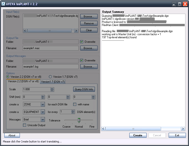
Use the Import-DGN window to choose the input and output files.
|
•
|
Click Clear to remove all files from the list.
|
|
•
|
Click Browse to select a macro or model file for output
|
|
•
|
If the Overwrite checkbox is selected, the output file can be overwritten without warning.
|
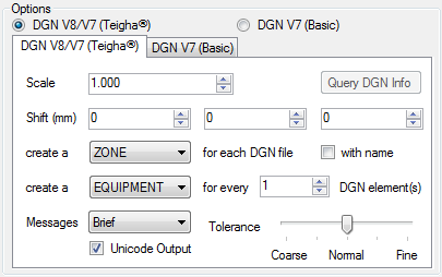
To translate a file with Import-DGN (Teigha® facilities), from the Options part of the window, select the DGN V8/V7 (Teigha®), and select the required options in the DGN V8/V7 (Teigha®) tab.
Scale enables the imported geometry to be scaled. A number larger than 1 makes the imported geometry bigger, and a number smaller than one makes the imported geometry smaller. A model can be corrected if the units in the DGN file are wrong, missing, or misinterpreted.
Shift (mm) shifts the whole model in E, N and/or U by the given numbers of millimetres. The a model can be positioned more conveniently, or simulate the MicroStation global origin.
Choose the number of messages to be written to the Output Summary and the Message file. The options available are Brief, Full or Debug. Debug is very verbose, and is primarily intended to help developers to investigate any issues with the translations of particular files.
The Unicode Output check box should normally be selected. Do not use this option if the macro is used in with older versions of PDMS.
Query DGN Info opens each DGN file listed, and writes some summary information about each into the Output Summary.
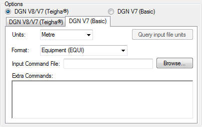
To translate a dgn7 format file with Import-DGN (Basic) technology, select the DGN V7 (Basic), and select the required options in the DGN V7 (Basic) tab.
Choose a suitable set of units. Query input file units opens the first dgn file listed, and display the units information found in it. Select a matching value from the Units drop-down. The possible choices are mm, cm, Metre, Inch, Foot, Yard.
Choose an output format, the possible values are Equipment (EQUI), Structure (STRU), Volume (VOLM), Review.
Enter or Browse for a file ImPlant - I1.exe commands, for example to set up Steel recognition.
Such commands may also be typed or pasted directly into the Extra Commands field.
The Status Bar at the bottom displays what the program needs before it can run a translation. Click Create.
When an Import-DGN (Teigha® facilities) translation is running, the status bar shows an estimate of the progress through the translation of the current file. Cancel is activated, and various items of information are listed to the Output Summary.
|
Note:
|
Cancel is not active in an Import-DGN (Basic facilities) translation.
|
For example, these commands should be run from the Monitor Command Window:
If ImPlant - I.exe is run from a Windows command prompt without arguments, an interactive "command-processor" session is started, but as an alternative several command-line arguments are available, refer to Command Line Arguments for further information.
|
1.
|
By default, all the primitives generated are under an EQUIPMENT element. Normally, all DGN entities are grouped under the same EQUI. However, when a CELL is encountered in the DGN file, a new EQUI is generated. When the import of the CELL is complete, the elements that follow in the DGN file are grouped below another new EQUI. To generate a separate equipment element for each primitive, the user can use the GROUPPRIMITIVES OFF command. The user can also use the GROUPPRIMITIVES command to limit the number of primitives in each EQUIPMENT, VOLM or STRUCTURE.
|
MicroStation works internally in terms of position units (also known as units of resolution), but also displays master units and sub-units (also known as working units). AVEVA E3D™ and Review work internally in millimetres, but can interact with the user in many other units.
In order to successfully translate a DGN file for AVEVA E3D™ or Review it is necessary to convert the units in the DGN file into millimetres. The DGN file contains two-letter abbreviations of the names of the master unit and the sub-unit, but these abbreviations are not standardised, and so the translation is not automatic.
To display the ISFF unit information from a file, use the Q UNITS command. For example, if the file being worked on is called example.dgn type:
In this case, the MicroStation user has chosen to use metres as the master unit, millimetres as the sub-unit, and has one eightieth of a millimetre as the position unit.
The recommended way to set the units is with the UNITS command. If the master unit is one of METRE (or METER), CM, MM, YARD, FOOT or INCH the user should use that keyword. In this case type:
as a metre is one thousand millimetres, but UNITS METRE is recommended.
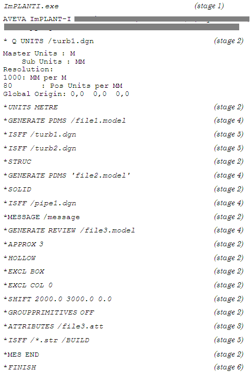
The following example shows a typical session using ImPlant - I.exe. Some of the commands in the example are described in detail in Notes on the Example Session.
|
Note:
|
Text in italic indicates what is being entered by the user.
|
Open a AVEVA E3D™ MODEL macro file called file1.mac which holds the AVEVA E3D™ commands for importing 3D data taken from the DGN files specified by the next ISFF commands. Every GENERATE command closes down any previous opened files.
Read the file turb1.dgn for 3D data and generate the commands for import to AVEVA E3D™ MODEL. The primitives generated are under the ZONE element called /turb1.dgn as no zone name was specified.
After giving this command, any DGN surfaces are output as solids. The command should be used, for example, when exporting pipes, so that tubes or bends are exported as cylinders and circular toruses and not as faceted models. The SOLID command is the default and produces solid models.
By default, all generated top-level AVEVA E3D™ elements are of type EQUIPMENT. To change this to STRUCTURE use the STRUC command and the VOLM command to change to VOLUME elements.
The STRUC command sets the mode so that the ISFF command generates the hierarchy STRUC/SUBST/Geometric primitives (BOX). The EQUIP command sets the mode so that the ISFF command generates the hierarchy ZONE/EQUIPMENT/Geometric primitives (BOX). In EQUIPMENT mode, the primitives are packed into the same EQUI until a MicroStation CELL entity is encountered. Then a new EQUI is generated. If GROUP ON is set in addition to EQUIPMENT mode then a new EQUI is generated for each micro station primitive.
|
Note:
|
The VOLM command does exactly the same as the EQUIP command but replaces all EQUIPMENT elements with VOLUME elements.
For all geometry files processed by following ISFF commands, process the corresponding attribute files with the same names and output the results in an AVEVA Attributes file named file3.att. The attribute files normally have the file extension .drv, and their format is shown in Attribute Translation.
The ATTRIBUTES filename command opens a new attributes file and switches attribute processing on. Opening an attributes file closes any attributes file that is already open. ATTRIBUTES END closes the attributes file. The output of attributes can be toggled on and off.
|
Note:
|
Import-DGN maintains cell ownership and Review segments within a cell segment inherit the attributes of the cell segment. In other words, the segments within a cell do not have attribute entries within the AVEVA Attributes file, only significant segments do.
|
Read all files with extension .str which have been generated by MicroStation and append the primitive records to the Review file file3.model. Standard windows wild-card characters may be used.
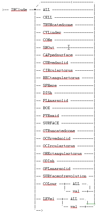
From now on do not export boxes. To include them back again in this example the commands INCLUDE ALL or INCLUDE BOX can be used.
After this command has been given, primitives with colour 0 are not exported. To include primitives with colour 0 again, the commands INCLUDE ALL or INCLUDE COL 0 can be used.
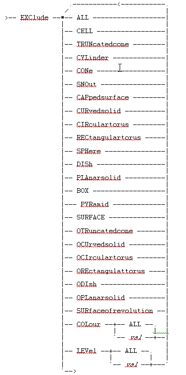
Most of the EXCLUDE/INCLUDE options are self-explanatory. However there are some options that describe MicroStation type of primitives/records and others describe 3D type of models as generated by ImPlant - I.exe.
Other element types referenced by the EXCLUDE command:
The MESSAGE command specifies an output file where all user commands and output messages can be stored. The MES END command closes the file.
These may be passed to ImPlant - I.exe by the usual command processor $m mechanism; for example:
|
2.
|
Run ImPlant - I.exe using the REPORTSTEEL ON command for discovering any possible steel structures (include profiles_british.imp and/or profiles_din.imp if appropriate). Import-DGN responds with one or more possible Steel Structure profiles.
|
The ADDSTEEL command has the format:
ADDsteel spec_name
x y (times number of points)
REPortsteel ON report on possible profiles
REPortsteel OFF do not report on possible profiles (default)
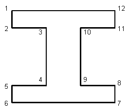
For each DGN projected surface, the program compares the profile of the surface with the profiles stored. If it finds a match, the program then generates Framework and Section elements. The Section element provides the SPRE, POSS, POSE, BANG, DRNS and DRNE attributes (refer to the Model Reference Manual for definitions of these attributes). The attribute SPRE is set to the spec_name as given in the Profile file.
The STEELTOLERANCE command may be used to change the tolerance used in this matching process.
ImPlant - I.exe normally requires that surfaces made by using rules, such as capped surfaces, shall have their caps classified as PRIMARY and their rules as PRIMARY RULES.
To allow ImPlant - I.exe to accept such surfaces, in which there is always exactly one element in each cap and both the caps and the rules are classified as PRIMARY, type the command:
To allow ImPlant - I.exe to accept surfaces where the rules are classified as CONSTRUCTION RULES, type the command:
|
Process the specified macro file (Refer to ImPlant - I.exe Profile Macro for further information)
|
|
|
Set the output window size. If the number of lines is negative the window appears minimised. If lines equals 0 the window does not appear.
|
The ADDSTEEL command defines a steel profile in ImPlant - I.exe. The corresponding profile must be defined in the AVEVA E3D™/Outfitting Catalogue.
The APPROX command sets the curvature approximation (chord tolerance). Values between 1 and 10 are allowed. The default is 5.
>-- APProximate -- val -->
The ATTRIBUTES name command opens a new attributes file and switches attribute processing on. Use the ATTRIBUTES text variant if the filename is to contain spaces. Opening an attributes file closes one that is already open. ATTRIBUTES END closes the attribute file. The output of attributes can be toggled on and off. The ATTRIBUTES EXTENSION command allows the file extension of the associated file (by default, drv) to be changed.
The EQUIP command sets the mode so that the ISFF command generates the hierarchy Zone/Equipment/Geometric primitives (Box). In EQUIPMENT mode, the primitives are packed into the same EQUI until a MicroStation CELL entity is encountered. Then a new EQUI is generated. If GROUP ON is set in addition to EQUIPMENT mode, a new EQUI is generated for each micro station primitive.
The EXCLUDE command can be used to control which primitives are translated. The user can exclude primitives by type, by colour or by level. Refer to the INCLUDE command for further information.
The EXCLUDE LEVEL command has an extended form not shown in the picture to exclude several levels in one command; for example:
The EXTENSIONS command tells ImPlant - I.exe how to deal with certain non-standard constructions found in some DGN files (refer to ISFF Extensions for further information).
The FINISH command exits from AVEVA ImPlant - I.exe.
The GENERATE command opens a named file for input into Review or AVEVA E3D™. Any previously opened files are closed. The filename can be given as a name (with a leading /) or as text (enclosed in single quotes). If the filename contains spaces the text form must be used. If the supplied filename does not have an extension, ImPlant - I.exe adds .mac for a AVEVA E3D™/Outfitting macro file, or .rvm for a Review model file. AVEVA E3D™ is accepted as an alternative to MACRO for backwards compatibility.
>-- GENerate --+-- MACRO ----.
| |
‘—- REVIEW --+-- filename -->
| |
‘—- REVIEW --+-- filename -->
The GROUPPRIMITIVES command affects how ImPlant - I.exe groups the Review and AVEVA E3D™ primitives. GROUPPRIMITIVES should be switched off if attributes are to be output.
The HOLLOW command specifies that DGN surfaces are output as surfaces, and not solids, which is the default.
The INCLUDE command is the opposite of EXCLUDE; that is, excluded options are included for export again. Refer to the notes on EXCLUDE and the example in Example ImPlant - I.exe Session, for further information on primitive types.
The ISFF command reads a named input file and generates a Review model file or a AVEVA E3D™ macro file. The filename can be given as a name (with a leading /) or as text (enclosed in single-quotes). If the filename contains spaces the text form must be used. If the filename does not contain spaces then wildcards can be used to read in several files at once. For example, on Windows:
Specify the name of the AVEVA E3D™ Zone as a name (with a leading /). If a new Zone element is not required, use the CONTINUE option to continue with the current zone. If a Zone without a name is required use the ANONYMOUS option. If no Zone name is given and neither of the other options is specified, then the Zone name is created from the input model filename.
>-- ISFF -- filename --+-- zonename ---.
| |
|-- CONtinue ---|
| |
|-- ANOnymous --|
| |
‘---------------+-->
| |
|-- CONtinue ---|
| |
|-- ANOnymous --|
| |
‘---------------+-->
The MESFIL command controls the message file and related facilities.
To send messages only to the standard output use MESSAGEFILE END.
The filename (if required) can be given as a name (with a leading /) or as text (enclosed in single quotes). If the filename contains spaces the text form must be used.
To control echoing of commands from a macro to the message file use the ECHO ON and ECHO OFF commands. If using a lengthy standard macro, include an ECHO OFF at the start and an ECHO ON at the end of the macro. The command can be used, for example, in the supplied steel section macros.
To write a message directly to the message file use the MESSAGEFILE PRINT message command. The message must be enclosed in single quotes.
>-- MESsagefile --+-- filename ----------.
| |
|-- COPy -- filename --|
| |
|-- END ---------------|
| |
|-- ECHo --+-- ON -----|
| | |
| `-- OFF ----|
| |
`-- Print-- message ---+-->
| |
|-- COPy -- filename --|
| |
|-- END ---------------|
| |
|-- ECHo --+-- ON -----|
| | |
| `-- OFF ----|
| |
`-- Print-- message ---+-->
Use the PDMSCOMMAND command to write an AVEVA E3D™ command directly to the AVEVA E3D™ macro file, either at once or at the start of each Equipment. Each command must be enclosed in single quotes. Use two single quotes to represent a single quote within the command. For example:
>-- PDMScommand --+-- command ----------------------.
| |
`-- EAChequipment --+-- command --|
| |
`-- OFF ------+-->
| |
`-- EAChequipment --+-- command --|
| |
`-- OFF ------+-->
Use the QUERY command to query the units used in a MicroStation file. The master units, sub-units and unit-of-resolution are output. The filename can be given as a name (with a leading /) or as text (enclosed in single quotes). If the filename contains spaces the text form must be used.
>-- Query --+-- units -- filename --.
| |
|-- SETtings -----------|
| |
`-- TOLerances ---------+-->
| |
|-- SETtings -----------|
| |
`-- TOLerances ---------+-->
The REMSTEEL command disables the matching of profiles while in ImPlant - I.exe. The command removes the matching of all previously defined profiles. Refer to the ADDSTEEL command for further information.
The REPSTEEL command controls reporting on possible profiles. Reporting can be restricted to profiles with fixed length.
The SOLID command specifies that ISFF surfaces are output as solids, which is the default. To specify that surfaces should be used to produce hollow primitives, use the HOLLOW command.
use the STEELFILTER command to selectively include or omit elements recognised, or not recognised, as catalogue sections (refer to STEELFILTER Command for further information).
Use the STEELTOLERANCE command to set the tolerance (in mm) used when matching steel sections.
>-- STEELTOLerance -- tolerance -->
The STRUC command sets the mode so that the ISFF command generates the hierarchy STRUC/SUBST/Geometric primitives (Box). The alternatives are the EQUIP and VOLM commands.
The TOLERANCE command is provided for the rare cases when altering the tolerances can improve the translation.
TOLERANCE DEFAULT restores the recommended values.
TOLERANCE FACTOR scales all the tolerances in proportion, and should be the first option to try if tolerances are to be adjusted. A factor of 1.0 is the same as DEFAULT, a factor of 2.0 loosens the tolerances, and a factor of 0.5 tightens them.
>-- TOLerance --+-- DEFault -----------.
| |
|-- Query -------------|
| |
|-- FACtor -- factor --|
| |
|-- NUMber -- value ---|
| |
|-- ANGle -- value ----|
| |
|-- VECtor -- value ---|
| |
|-- POInt -- value ----|
| |
|-- POLygon -- value --|
| |
`-- NORmal -- value ---+-->
| |
|-- Query -------------|
| |
|-- FACtor -- factor --|
| |
|-- NUMber -- value ---|
| |
|-- ANGle -- value ----|
| |
|-- VECtor -- value ---|
| |
|-- POInt -- value ----|
| |
|-- POLygon -- value --|
| |
`-- NORmal -- value ---+-->
Specifies the size of a MicroStation master unit, by name or in millimetres, refer to Units in ImPlant - I.exe for further information.
The VOLM command sets the mode so that the ISFF command generates the hierarchy Zone/VOLuMe/Geometric primitives (Box). In VOLuMe mode, the primitives are packed into the same VOLM until a MicroStation CELL entity is encountered, when a new VOLM is generated. If GROUP ON is set in addition to VOLuMe mode, a new VOLM is generated for each micro station primitive.
ImPlant - I.exe assumes the following format for the attribute files that it reads in using the ATTRIBUTE command:
keyword <blank>{<blank><attLink><blank>text<blank>{<attVal><attVal>
Refer to Basic facilities or Teigha® facilities and Preparing for an Teigha® Technology Translation for further information.
Refer to Basic facilities or Teigha® facilities and Preparing for an Import-DGN Basic Technology Translation for further information.
Details of this output, particularly at full and debug levels of detail are likely to change significantly from release to release to provide more useful information for support calls.
These errors may cause elements to be skipped, or in some cases cause the whole translation to stop.
Messages reported by the Import-DGN window can include messages from Translation Messages or Import-DGN (Basic facilities) Warnings and Errors as well as messages such as the following:

