Equipment
Equipment : Import/Export MEI : Import Model
The imported models may be individual components that can be used to model Equipment items in MODEL, or they may represent part of the overall model that has been produced in another CAD system and needs to be combined with the Design model for visualisation, clash checking, drawing and other operations.
The input to Import utility consists of STEP AP203 files that normally have the file extension .stp. Geometrical data is read from the input AP203 files and converted into Equipment or Volume Model elements in a Design database. Several AP203 files can be loaded in one process, each file generating an Equipment or Volume Model element.
Models imported from STEP AP203 files can be stored in Design Database Application Data World element hierarchies. Typically, one or more Application Data World (APPDWL) elements with Purpose attribute set to MIMP is created in a Design database separate from other Design data elements, this is the holding area for imported models. Here the imported models are organised into logical groups, for example by engineering function, and they may be modified to include additional geometry that may be required in the Design model, such as connection points for Drafting dimensions and Design Associations; primitives representing reserved space for clash checking and nozzles for piping connections. The imported primitives may themselves be modified to change the name, drawing level and obstruction level attributes to conform to company standards.
Use the MEI Import window to import models or to find and modify GENPRI and GENCUR elements, refer to Import and Modify for further information.
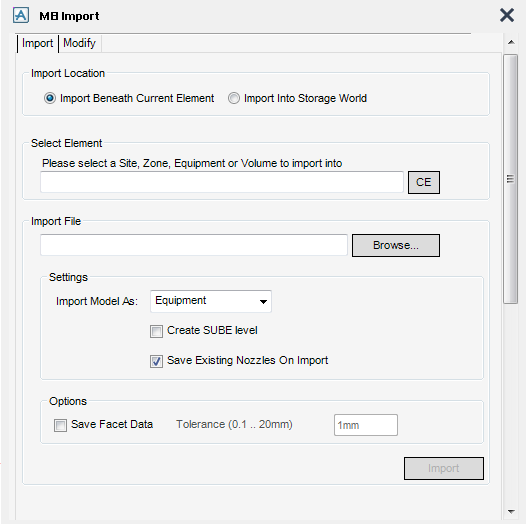
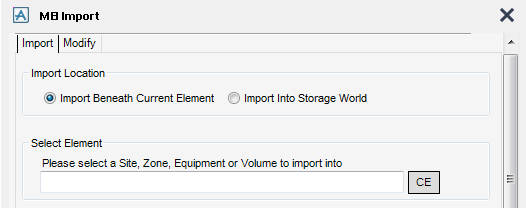
Use the Import tab to either import models beneath an existing element in the hierarchy or to import into a storage area by clicking either the Import Beneath Current Element or the Import Into Storage World radio button.
To import beneath an existing element, select Import beneath current element and in the Model Explorer select the Site, Zone, Equipment or Volume to import beneath and click CE. The selected element displays in the Select Element field.
To select the file to be imported click Browse to display a file browser, navigate to the .stp file and select it. The selected file name displays in the Import File field.
|
Note:
|
Choose how the model data is imported by selecting either Equipment (EQUI), Volume Model (VOLM) or Subequipment from the Import Model As drop-down menu.
If required, click to select the Create SUBE level check box to create a subequipment level in the MODEL hierarchy.
When re-importing the same model into the same area, the option to save any existing nozzles in that area is available, click to select the Save existing nozzles on import check box. If the Save existing nozzles on import check box is not selected, then any nozzles that exist are deleted. A warning message displays to confirm this.
When re-importing the same model into the same area, the option to save facet data along with a tolerance in that area is available, click to select the Save Facet Data check box and enter the required tolerance into the Tolerance (0.1 .. 20mm) field.
Click Import to begin the import process.
|
Note:
|
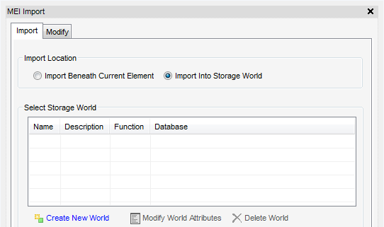
To import into an Application Data World (APPDWL) hierarchy, select the Import Into Storage World. If the project contains existing storage worlds, these are displayed in the Select Storage World pane.
Click Create New World to create a new model import storage world (an APPLDW element with purpose attribute = MIMP), an Application Data Area (APPDAR) and Application Data Group (APPLDA) which is the basic structure needed to import into.
To modify the model import storage world's attributes, select from the Select Storage World list and click Modify World Attributes.
|
Note:
|
If the storage world is new the Modify Attributes fields are blank.
|
If required, the values in the fields can be modified then click Apply to store the new values in the database. The new values are displayed in the Select Storage World list. Click Back to cancel the changes and return to the original window.
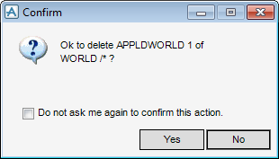
To delete a storage world and all the imported models in that world, select the storage world from the Select Storage World list and click Delete World. A Confirm window displays requesting confirmation.
Select Yes to confirm the deletion or No to cancel the deletion and return to the MEI Import window.
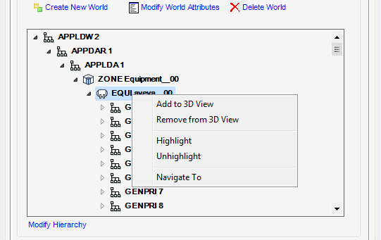
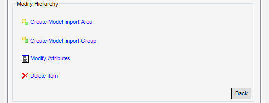
Click Modify Hierarchy to display a list of tasks to modify the hierarchy of the storage world.
Tasks in the list are active depending on what is selected in the tree. To return to the Import file panel, click Back.
To select the file to be imported click Browse to display a file browser, navigate to the .stp file and select it. The selected file displays in the Import File field.
Once the location where the file is to be imported is highlighted in the tree and the Import File field have been populated, Import becomes active.
|
Note:
|
Choose how the model data is imported by selecting either Equipment (EQUI), Volume Model (VOLM) or Subequipment from the Import model as drop-down menu.
If required, click to select the Create SUBE level check box to create a subequipment level in the MODEL hierarchy.
When re-importing the same model into the same area, the option to save any existing nozzles in that area is available, click to select the Save existing nozzles on import check box. If the Save existing nozzles on import check box is not selected, then any nozzles that exist are deleted. A warning message displays to confirm this.
When re-importing the same model into the same area, the option to save facet data along with a tolerance in that area is available, click to select the Save Facet Data check box and enter the required tolerance into the Tolerance (0.1 .. 20mm) field.
Click Import to begin the import process.
|
Note:
|
Imported VOLM and EQUI elements contain GENPRI and GENCUR elements. These are the imported solid and curve objects. GENPRI and GENCUR elements can be moved, rotated and deleted by using the same menu and Model Editor functions as other Equipment primitives. However, the geometry of the shape cannot be modified in Outfitting/Design. GENPRI and GENCUR elements cannot be modified with the Modify Properties utility. Use the Export MEI functionality to find and modify GENPRI and GENCUR elements.
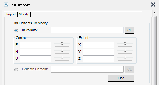
The Find Elements to Modify pane of the MEI Import window provides access to the search criteria to find GENPRI and GENCUR elements to modify.
Use the In volume functionality to find all the elements (of type GENPRI, GENCUR, NOZZ, SUBE, BOX and CYLI) within a volume. Select an element in the Model Explorer, for example, the owning Equipment of an imported model, then press CE.
A bounding box is placed around the current element in the graphical view. The box's position and size and can be modified by using the Centre and Extent sliders. When Find is clicked, any elements found within the volume that belong to the current element are displayed in the grid.
To find all elements (of type GENPRI, GENCUR, NOZZ, SUBE, BOX and CYLI) beneath the specified element. Select Beneath element then select an element in the Model Explorer, for example, the owning Equipment of an imported model, then press CE. When Find is pressed, any elements that are members of the specified element are displayed in the grid.
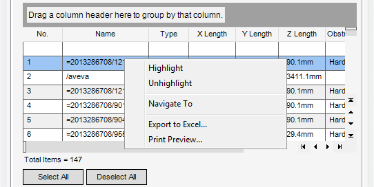
Click items on the grid to select them. Items can be multi-selected by using the Ctrl key and clicking on an item and dragging down. Select All selects all items in the grid and Deselect all deselects all items in the grid. The pop-up menu on the grid allows the user to Highlight, Unhighlight, Navigate To selected elements, Export to Excel or Print Preview.
The Display level and Obstruction level attributes displayed on the Representation pane are set to default values when the model is loaded. These values can be modified, by selecting items in the grid, then click Apply to store the new values in the database.
Box and Cylinder primitives can be generated from items in the grid. Select items from the grid and then choose the Primitive by selecting Box or Cylinder from the drop-down menu. Click Create to create either the boxes or cylinders.
GENPRI and GENCUR elements do not have P-points. Some facilities, such as dimensioning in Draft and Associations in MODEL, rely on having connection points to reference. Design points can be added to Equipment by using the Create > Points Equipment menu command. These behave like P-points belonging to the Equipment element.
Standard Design primitives can be added to imported models by using the functionality available from the GUI, refer to Model Equipment for further information.
Nozzles and electrical components can be added to imported Equipment by using the Create Nozzles and Create Electrical Component options on the Create Connections pane of the MEI Import window. Refer to Nozzle and Electrical Component for further information.
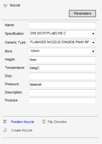
Click Parameters to display a plot file as displayed on the Create Nozzle window after Create Nozzles is selected. Use the window to Name the nozzle, select a nozzle from the current MDB and enter various attribute details.
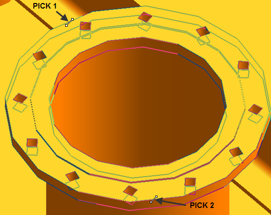
After clicking Position Nozzle, the prompts to identify an edge for the nozzle face by picking two points on a circumference of the nozzle on the required GENPRI element are displayed.
Once the position has been selected, Create Nozzle and Flip Direction become activate. The measured diameter is also displayed under the Purpose field.
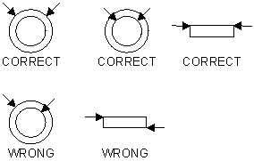
If the direction arrow is in the opposite direction to that required, click Flip Direction to reverse the direction and update the aids. The plane aid provides feedback if the edges picked are not in the same plane.
To create the nozzle, click Create Nozzle. The created nozzle is based on the picked position and orientation and the selected attributes. Once the nozzle has been created it displays in the graphical view and the Create Nozzle window is reset ready for the next nozzle pick.
Design Points, coupled with Create Nozzle, add some intelligence into the imported geometric model. Once positioned these design points can be selected in the same manner as conventional p-points can be in graphical selection modes and when drawing or annotating in draft.
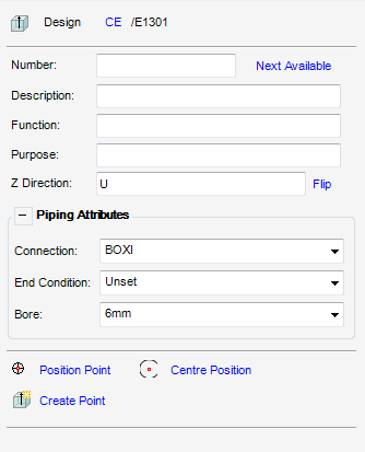
To create a Design Point, select the equipment element in the explorer and click Create Design Points to display the Create Design Point window.
The equipment element displays at the top of the Create Design Point window and can be changed by selecting a different equipment element in the explorer and clicking CE.
Each design point must have a unique positive number for each equipment item, enter a number in the Number text field. The number is validated by the system and changed to the next available number if it's found to be already in use. Or leave the Number field blank and click Next Available to let the system pick the next available number.
Add a Description, Function and Purpose to the created point. The Direction field sets the direction of the point. Once a value is entered, that value is checked to make sure it is a valid direction. Click Flip to reverse the direction and update the field.
The Piping Attributes for the Design Point can also be set.
Click Position Point to pick a position for the point using the standard positioning functionality.
|
Note:
|
It is recommended that the standard positioning functionality is set to Graphics when picking GENPRI elements.
|
After clicking Centre Position, the prompts to pick two edges of a feature are displayed. The two edge picks are converted to a position at the centre of the picked feature with the direction normal to the plane on which the two points are picked. To create the Design Point, click Create Point.
AP203 files can be imported to MODEL by using the IMP command. The IMP command can be used in command macro files to automate the loading of AP203 files.
The IMP command has the following options:
Imports model.stp found under the directory C:\AP203Models to a SITE or APPLDA element called /IMPORTAREA. A ZONE element is created and a VOLM element is created for the *.stp file.
Imports model.stp found under the directory C:\AP203Models to the current element, which must be a SITE or APPLDA type element. A ZONE element is created and a VOLM element is created for the *.stp file.
Import all .stp files found under root directory C:\AP203Equipment to the current element. A ZONE element is created for each folder in the C:\ AP203Equipment hierarchy. Within each ZONE, an EQUI element is created for each .stp file in the corresponding folder.
When models are imported, the ZONE and EQUI or VOLM elements are named automatically. The name used is based on the folder name and the .stp filename. If a model is imported more than once, a suffix is added to the filename so that the names of new elements remain unique.
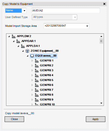
Use the Copy Model to Equipment window to navigate to imported models and copying selected models to Equipment elements in the Design model.
From the Model Import Storage Area options, select the storage area from which to select an imported model. The storage area hierarchy displays the in the explorer view.
Navigate to the required import model using the Explorer and click Apply. A Positioning Control window is displayed, use the facilities provided by this window to pick the position of the equipment's origin and complete the creation process. Refer to COMMON FUNC GUIDE.
|
|||
|
|||
|
|||
|

