DRAW Reference Manual
Dimensions : Linear Dimensions : Detail Attributes of Linear Dimensions
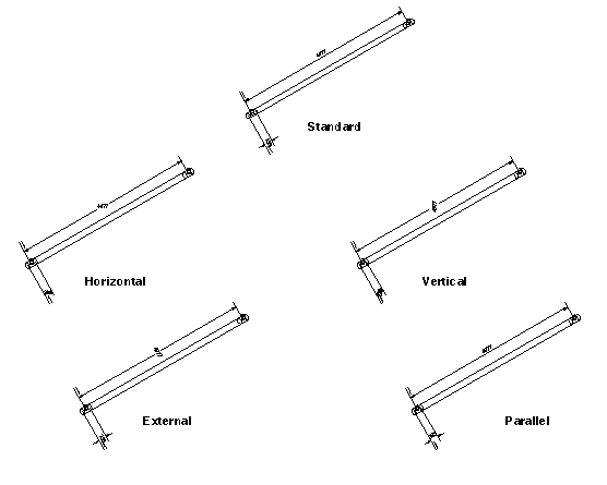
In a macro, the separation can also be set in terms of Sheet or screen coordinates. Note that the minimum separation is governed by the DMSP attribute - the calculated spacing cannot be less than this minimum. The example illustrates the effect of varying the spacing.
Dimension line text (DMTX) is set by a command of the form:
#DIM in the example takes the value of the dimension. #DIM is a simple case of intelligent text. Refer to Intelligent Text for further information. Note that in the case of non-truncated parallel dimensions, the dimension line spacing is automatically adjusted to accommodate two or more lines of text if these are input. Dimension line text can be set at Dimension Point or Dimension level, although in the latter case the text input is attached to all the dimension lines involved. Associated commands are:
|
- (at Dimension Point level): set dimension text to that of owning Dimension
|
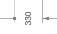
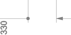
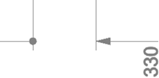
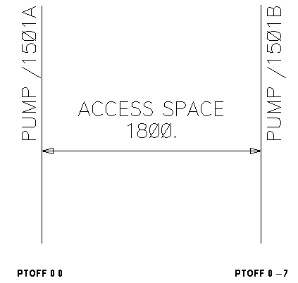
Dimension text is automatically centre-justified, but its position relative to the dimension line can be varied by changing the setting of the dimension text offset (DTOF) attribute. For example:
|
- DTOF defined by a ‘constructed point’. Refer to Point and Line Construction for further information.
|
Dimension text angle can be controlled using the DTANGLE attribute. The attribute is available both at dimension and dimension point level. Possible settings are:
Dimension line continuous mode (DLCNTMODE) flag is available on dimension points, dimensions and dimension styles. It is available on all dimension types, but it is most useful on linear dimensions. It is normally set on the end vertex of a dimension line segment, so that it only affects that particular segment.
Dimension line extended (DAEXLL) flag is available on the LDIM. When the flag is set, and the dimension lines are EXTERNAL, moving the text parallel to the dimension line extends the dimension line to stay in line with the end of the text.
Projection line text (PLTX) is set and manipulated in a similar way to dimension line text. For example, the commands:
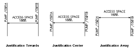
Projection line text axes are oriented relative to the projection line. The orientation is controlled by setting the PTOF attribute.
|
- PTOF defined by a constructed point. Refer to Miscellaneous Text Facilities for further information.
|
|
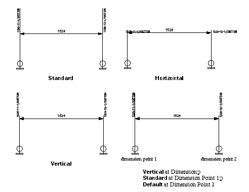
Projection text angle can be controlled using the PTANGLE attribute. The attribute is available both at dimension and dimension point level. Possible settings are:
The HORIZONTAL and VERTICAL settings cause the projection line text to be drawn respectively horizontally or vertically in the VIEW. In these cases, the projection line is not extended automatically to underline the text but only overshoots the dimension line by the distance specified by the OSHT attribute.
Initial settings of these attributes are cascaded down from LAYE level. Refer to Miscellaneous Text Facilities for further information.
|
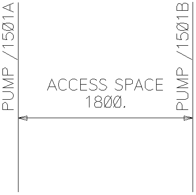
- Change dimension line text to ‘ACCESS SPACE’
|
|
|
- Change projection line text to 'ACCESS SPACE
|
|
Note:
|
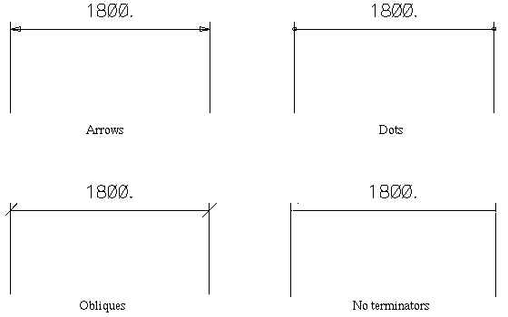
Dimension line terminators are arrowheads by default, but can be obliques, dots, or absent altogether.
|
Note:
|
The first terminator of a truncated dimension can be set independently using the FTER attribute. Refer to Detail Attributes of Linear Dimensions for further information. The first terminator is drawn 25% larger than the remainder.
|
At an LDIM the initial settings of these four attributes are cascaded down from LAYE level. At dimension point level their initial values are DEFAULT, for example, they use the values from the owning LDIM. Refer to Colours and Styles for further information.
Gaps in projection lines are most easily defined using the cursor, with either the start and end points or a mid point and a length being specified. Examples of the relevant commands are:


