Model Reference Manual
Structural Design Using Catalogue Components
:
Representing Building Components
: Controlling Edge Representation in DRAW
Controlling Edge Representation in DRAW
To plot walls and floors in DRAW, the user may want to remove the lines which represent common edges between such elements (referred to as 'unioning' the elements) to give a more realistic appearance. The elements used to represent buildings have an attribute specifically for this purpose: the DRAW
Union (DUNION)
attribute.
The elements to which this attribute applies are: Zone, Structure, Framework, Subframework, Compound Wall, Compound Floor and Compound Screed.
In each case, the DUNION attribute can take one of the following values:
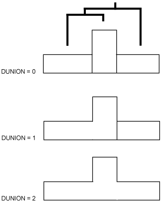
DUNION=0 Common edges always shown
All common edges between adjoining elements will be drawn in DRAW.
DUNION=1 Common edges not shown between members
Common edges between adjoining elements will be drawn in DRAW
unless
a pair of such elements are both members of a common parent, in which case the edge lines will be removed.
DUNION=2 Common edges not shown between members and peers
Common edges between adjoining elements will be drawn in DRAW
unless
a pair of such elements are
either
both members of a common owner
or
are at the same hierarchic level with a common parent, in which cases the edge lines will be removed.
In the simplest cases, the effects are as shown in the following diagram:
The overall effect in DRAW is determined by the composite effects of the settings for all significant elements (i.e. all elements which have a DUNION attribute) above those being drawn. For example:
When DUNION = 0, all members of the current element will be 'assembled' together rather than 'unioned': joint lines will therefore be shown between touching members (e.g. between adjoining Panels).
When DUNION = 1 for a FRMW or SBFR (or equivalent soft types), all members will be unioned: joint lines between touching members (e.g. adjoining Panels) with the same owner will not be shown. The FRMW or SBFR will not itself be unioned with another FRMW or SBFR.
When DUNION = 1 for a ZONE, STRU or FRWM, all member STRUs, FRMWs and SBFRs with DUNION = 2 will be unioned. Thus, joint lines will not be shown between adjoining Panels with different owners. The ZONE, STRU or FRMW will not itself be unioned with another ZONE, STRU or FRMW.
When DUNION = 2 for any element, all members with DUNION = 2 will be unioned, and the current element will also be unioned to others which share the same owner and which have DUNION = 2 as long as the owner has DUNION = 1 or 2.
Note:
The use of DUNION also affects the choice between displaying obscured or backface hidden lines. Backface is chosen where hidden lines are hidden by the same model element, while obscured is chosen when the hidden lines belong to another model element. The use of DUNION affects whether certain model elements are treated as a single element or separate elements and as a consequence affects the choice of obscured or backface.
1974 to current year.
AVEVA Solutions Limited and its subsidiaries. All rights reserved.