Model Reference Manual
Structural Design Using Catalogue Components
: Positioning and Orientating Using P-lines
Positioning and Orientating Using P-lines
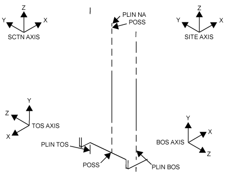
P-lines in a 3D structure represent lines, derived from points defined in the Catalogue for corresponding Profiles or Joints, which have associated direction vectors in the X-Y plane. A typical configuration for an ‘extruded’ I-section component is illustrated in
Figure 10:1.: Typical P-lines and Axes for a Section
; typical p-lines associated with a wider range of profiles are illustrated in the guide
Structural Design Using AVEVA E3D™
.
A p-line can provide a very convenient reference line or axis within an element’s 3D geometry (as derived in the design model) for positioning or orientating the element itself, or for defining some other geometry relative to the element. Positions may be defined along the length of a p-line; directions may be defined in terms of a p-line’s coordinate axes (the p-line direction being, by default, along its +Z axis).
Some examples have already been introduced in the earlier sections of this chapter. This section further illustrates the possible uses of such techniques.
Figure 10:1.
Typical P-lines and Axes for a Section
1974 to current year.
AVEVA Solutions Limited and its subsidiaries. All rights reserved.