Model Reference Manual
Piping, Ducting and Cable Trays
:
Orientation and Connection of Components
: Component Connection
Component Connection
Keywords:
CONNECT
Description:
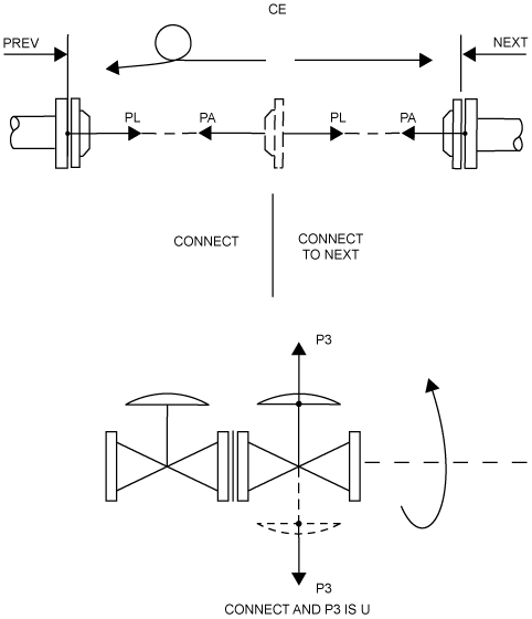
This command places a p-point on the current Component face-to-face with the p-point of an adjacent Component. If the Connection Types or nominal bores of the Connected faces are not compatible, MODEL automatically Flips (reverses Arrive and Leave) the Component and tries again. If the adjacent element is an Attachment Point (ATTA) then this is ignored and Connection is attempted on the Next Component.
Examples:
CONNECT
The arrive p-point of the Component is connected to the leave p-point of the Previous Component (see
Figure 8:9.: Component connection
).
CONNECT TO NEXT
The leave p-point of the Component is connected to the arrive p-point of the next Component (see
Figure 8:9.: Component connection
).
CONNECT AND P3 IS U
As first example
and
the off-line p-point is oriented upwards (see
Figure 8:9.: Component connection
).
Note:
Only adjacent Components (not Attachment Points) may be connected to; if Connection Types or bores are incompatible, then an automatic FLIP takes place and CONNECT is attempted again.
Command Syntax:
>- CONnect -+- <marke> -+- TO <marke> -+- AND <bdir> IS <bdir> ->
| | |
| | ‘-->
| ‘-->
‘-->
Querying:
.------------------<----------------.
/ |
>-- Query <marke> --*-- POSition --. |
| | |
‘--------------+-- WRT --. |
| | |
|-- IN ---+-- <gid> --’
|
‘-->
Figure 8:9.
Component connection
1974 to current year.
AVEVA Solutions Limited and its subsidiaries. All rights reserved.