Common Functionality
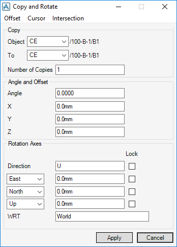
To specify the offsets as being the same as those between two existing design items, use the Offset menu options to measure the required distances. Use the submenus to specify the type of element you want to measure from and the type of element you want to measure to. The choices in each case are:
|
The Object drop-down menu allows you to specify the element to be copied. The choices are:
|
|||||||
|
The To drop-down menu allows you to specify where the copies are to be stored in the database. The choices are:
|
|||||||
|
Enter the Number of Copies required in the text field.
|
|||||||
|
The Offset must be specified in terms of the local X,Y,Z coordinates of the geometric primitives that make up the structural items, rather than the E,N,U coordinates used to position items within the overall design model. In this case, by default, X=E, Y=N and Z=U. The axes are displayed automatically in the graphical view as a guide.
Select the Lock check box to lock the selected coordinates.
|
|||||||
|
The Rotation Axis is displayed in the 3D graphical view as a guide.
|
|||||||
|
The Direction gives the axis in which the object rotates. The distance the rotated object is from the centre of the axis is determined by the figure in the East/North/Up text boxes.
Select Lock check box to lock the selected direction.
|
|||||||
|
The With Respect To (WRT) text box allows the selection of co-ordinates with respect to any design element. The default is World.
|
|||||||
Select the required options from the Offset menu and, when prompted, pick the two points between which the offset is to be measured. The calculated distances is entered in the Offset X,Y,Z text boxes automatically.
To specify the axis by reference to existing design items, use the Cursor menu options.
|
Prompts you to pick an element to which the position can be related to the required position. Use the Cursor Defaults setting to specify which point along a linear element (typically a Section) is to define the position.
|
|
|
Prompts you to pick a pline which passes through the required position. Use the Cursor Defaults setting to specify which point along the pline is to define the position (the pline is here considered to extend from the POSS to the POSE of the SCTN to which it refers).
|
|
|
Prompts you to pick a panel edge which passes through the required position. Use the Cursor Defaults setting to specify which point along the edge is to define the position.
|
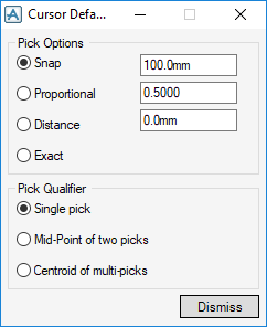
Select Cursor > Defaults to display the Cursor Defaults window, which allows you to set the way pointer picks are interpreted when you pick a position in a graphical view.
|
The Pick Options pane specifies how a pick along a linear item (section, pline, edge) is to be interpreted as a position. Select the following choices:
|
|
Select Intersection menu options to define a position by picking two directional items using the cursor in a graphical view.
Click Apply to create the rotated copy and, when prompted, confirm that you want to retain the copy. Use the same procedure to rotate copy and reflect a second member to create a third member.


