Common Functionality
Settings : Graphics
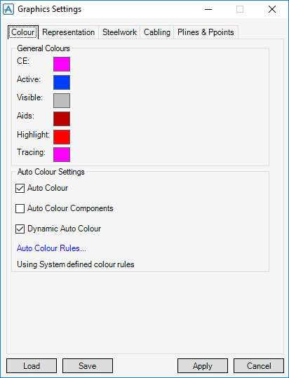
The Graphics settings window has the following tabs:
|
•
|
|
•
|
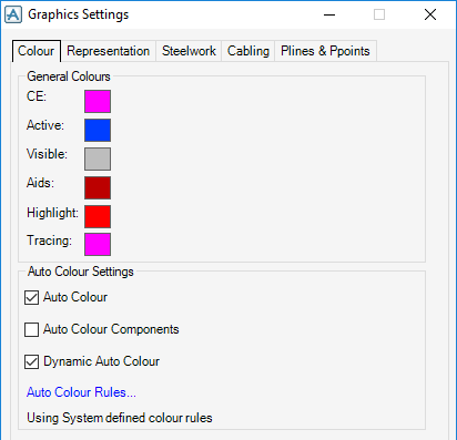
The General Colours pane has the following options:
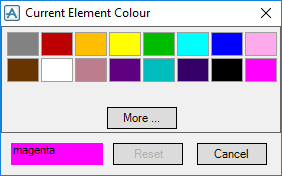
To change any of these colours, click on the coloured square to the right of the name, for example CE.
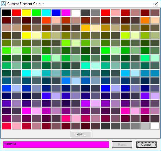
Select the new colour from the displayed Current Element Colour window.
Click More to access the full palette.
Refer to Auto Colour Settings for further information.
Sets the translucency of displayed elements. The degree of opaqueness can be controlled by selecting the required percentage translucency from the drop-down list, Solid (0%) colour to 100% is completely transparent.
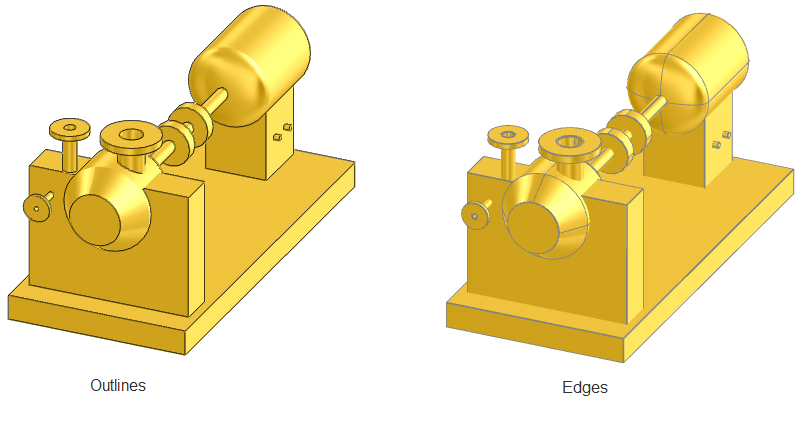
Toggles Edges On/Off. Select Edges to display edges to those elements discovered by the applying the rule.
Select Auto Colour check box to assign the colours to the significant elements when they are added to the Drawlist. Auto Colour is selected by default, meaning that the default auto-colour rules are to be used.
Select Auto Colour Components check box to re-evaluate the colour for element components.
Select Dynamic Auto Colour check box to re-evaluate the colour rule for that element.
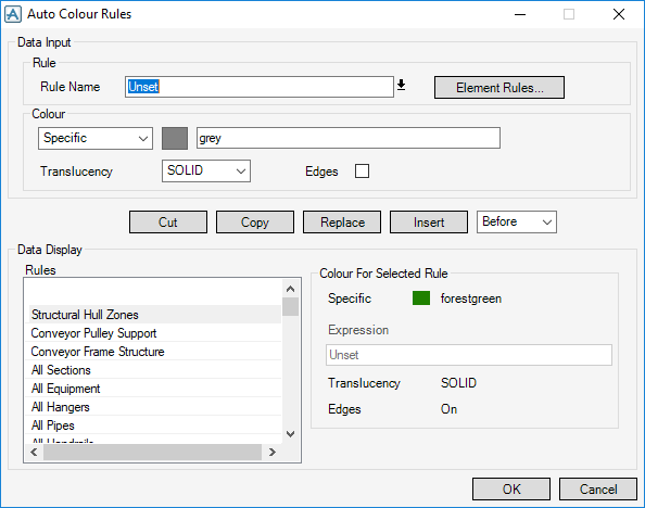
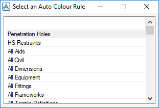
To change the colour for a rule, click on the down arrow beside the Rule Name text box, to display the Select an Auto Colour Rule window. Select the rule from the displayed list.
|
From the Colour pane drop-down list select a Specific colour or apply an Expression to the choice of colour.
|
|||
|
If Specific is selected, click on the coloured box and select the required colour from the displayed selection window and click Dismiss.
|
|||
|
If Expression is selected, enter the required expression into the text box.
|
|||
|
Select the Translucency drop-down list to set the translucency of displayed elements to allow you to see through the translucent items to the items behind them in display. The degree of opaqueness can be controlled by selecting the required percentage translucency from the drop-down list, you can select Solid (0%) colour to 100% is completely transparent.
|
|||
|
Select Edges check box to display edges to those elements discovered by the applying the rule.
|
|||
|
|||
|
If you want to copy a rule from the list, highlight it and click Copy. The rule is displayed in the Data Input pane, allowing you to change the name and insert it back into the rules list.
|
|||
|
If you want to rearrange the Rule list you can select a rule and click Cut and then Replace it in the order that is required.
|
To retain the changes and close the window, click OK or click Cancel to close the window without retaining any changes.
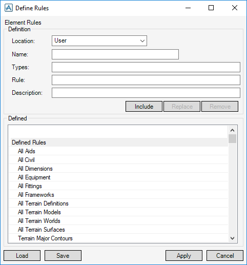
To create a new rule or modify an existing one, click Element Rules, to display the Define Rules window.
|
Rules can be located in several areas. Dependent on the selected Location using the drop-down rules are stored in:
|
|
|
For example, BSP\bspdflts\des-element-rules.pmldat
|
|
|
Enter a Name for the new rule in the text box.
|
|
|
Enter the Types in the text box, which is a standard four-letter word which defines the type of element in the Design database hierarchy.
|
|
|
A logical selection Rule must be defined to identify any type of element for which the Type alone is not a sufficient specification. A selection rule is defined as the evaluated result of a PML expression.
|
|
Click Include or Replace (an existing rule), if you want to save the changes it has made and then click Apply to close the window.
To bring the rule into use, you must add it to the list of rules on the Auto Colour Rules or Naming Rules window.
Once you have completed configuring the Colour settings, click Apply to apply the settings. Click Cancel to discard any changes made.
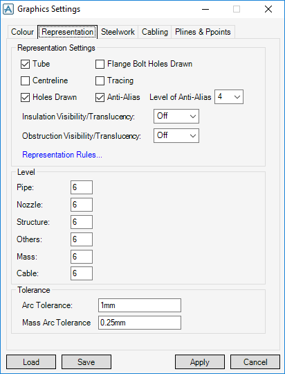
The Representation tab of the Graphics Settings window allows you to set some of the general and piping representation parameters and presents control options allowing you to display further windows for specifying the representations of more specific parameters.
|
Select Tube check box to display double line representation of piping components.
|
|||||||||||||
|
Select Centreline check box to display single line representation of piping components.
|
|||||||||||||
|
Select Holes Drawn check box to display holes (negative primitives) as true holes, rather than as black lines in a shaded view.
|
|||||||||||||
|
Select Flange Bolt Holes Drawn check box to display bolt holes drawn on flanges.
|
|||||||||||||
|
Select Tracing check box to display tracing.
|
|||||||||||||
|
Select Anti-Alias check box to display anti-alias lines. The Anti-Alias level determines how fine a diagonal line is drawn; the higher the number the finer the line. However, the higher the level the more computer workstation CPU is required.
|
|||||||||||||
|
If selected, Insulation Visibility/Translucency is displayed on the piping components and tubing, as defined in the catalogue. Click on the drop-down menu to specify a level of translucency between 0% (Off) and 100% (Solid).
|
|||||||||||||
|
If selected, Obstruction Visibility/Translucency volumes are displayed, as defined in the catalogue (but only if the drawing level is set appropriately). Click on the drop-down menu to specify a level of translucency between 0% (Off) and 100% (Solid).
|
|||||||||||||
|
|||||||||||||
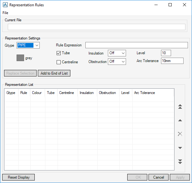
Click Representation Rules, to display the Representation Rules window. You can Create, Edit, Save and Load various representation rules, to be applied to various element types.
Rules can be set from the Representation Settings pane:
|
Select the Gtype element (Generic type) from the drop-down menu.
|
|
|
Enter a Rule Expression in the text box (for example bore gt 80mm), if required.
|
|
|
Select Tube check box to display double line representation of piping components.
|
|
|
Select Centreline check box to display single line representation of piping components.
|
|
|
If selected, Insulation is displayed on the piping components and tubing, as defined in the catalogue. Click on the drop-down menu to specify a level of translucency between 0% (Off) and 100% (Solid).
|
|
|
If selected, Obstruction volumes are displayed, as defined in the catalogue (but only if the drawing level is set appropriately). Click on the drop-down menu to specify a level of translucency between 0% (Off) and 100% (Solid).
|
|
|
Enter the drawing Level for the relevant Gtype element. In each case, enter the required level (which must be in the range 1-99).
|
|
|
Click Replace Selection to replace an existing representation rule.
|
Once you have added or replaced a representation rule, click Apply to apply the rules to the graphical display.
To restore the display to the default settings, click Reset Display.
To save Representation Rules set, select File > Save or to load a created rule set select File > Load.
Once you have completed configuring the Representation settings, click Apply to apply the settings. Click Dismiss to discard any changes made.
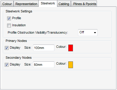
The Steelwork tab allows you to change the way Steelwork elements are displayed. Structural steel profiles can be represented by a single Centreline or by a 2D outline. In some cases, it helps to switch between the two representations to simplify an otherwise complicated view. You can change these settings as well as other common display settings for Steelwork.
|
Select Profile check box to give a full multi-line profile representation, as defined in the catalogue.
|
|
|
Select Insulation check box to display the insulation on structural items, as defined in the catalogue.
|
|
|
The Profile Obstruction Visibility/Translucency drop-down menu allows you to select obstruction volume representation to be Off (Solid) or to have the selected translucency value.
|
The settings for Primary Nodes and Secondary Nodes are specified independently. If either or both types of node Display check box is selected, they are displayed as crosses of the specified Size and Colour. Set these options as required.
Once you have completed configuring the Steelwork settings, click Apply to apply the settings. Click Dismiss to discard any changes made.
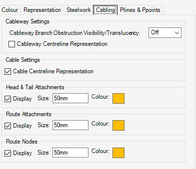
The Cabling tab allows you to change various display settings for Cabletray elements.
|
Select the Centreline check box to display the centreline representation of the cableways.
|
|
|
Select the Centreline check box to display the centreline representation of the cables.
|
Select Display check boxes for Head & Tail Attachments, Route Attachments and Routes Nodes to allow you to display or remove these elements from the 3D View with its specified Size and Colour.
Once you have completed configuring the Cabling settings, click Apply to apply the settings. Click Dismiss to discard any changes made.
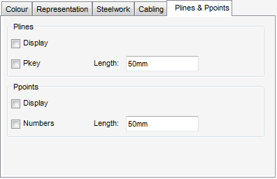
Plines and Ppoints representation for structural Profiles can be set on display or off display. By default Plines and Plines are not displayed, although p-points is displayed automatically as part of an identification operation.
|
Select Display check box to display Plines as arrows of the length specified from the Length text box.
Select Pkey check box to display Pkey numbers (TOS, BOS, NA) next to the arrows
|
|
|
Select Display check box to display Ppoints as arrows of the length specified from the Length text box.
Select Numbers check box to display Ppoint numbers next to the arrows.
|
Once you have completed configuring the Plines & Ppoints settings, click Apply to apply the settings. Click Dismiss to discard any changes made.

