DRAW Administrator Guide
Pipe Spool Drawing Administration : Sheet Template Administration
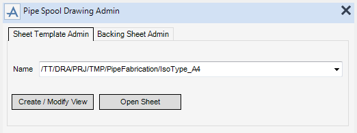
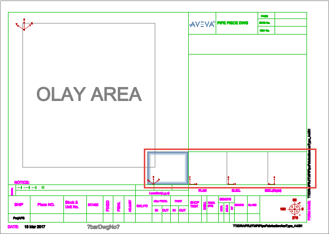
The Sheet Template Admin tab allows you to view and modify a pipe spool drawing template.
|
Click to display the drawing template modification options. Refer to Create / Modify View for further information.
|
|
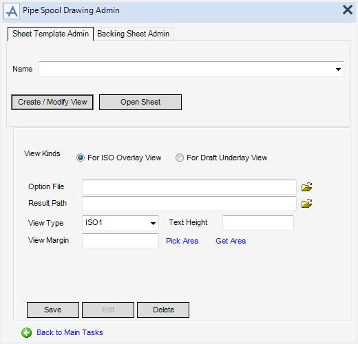
Select the For ISO Overlay View radio button to manage the ISO option file.
|
Input the file name of the iso view or click Browse to navigate to the required folder.
|
|
|
Click Pick Area to define an area for the iso view using two picked points on the drawing canvas.
Click Get Area to define an area for the iso view using an existing rectangle.
|
|
|
Click to return to the Pipe Spool Drawing Admin window main tasks.
|
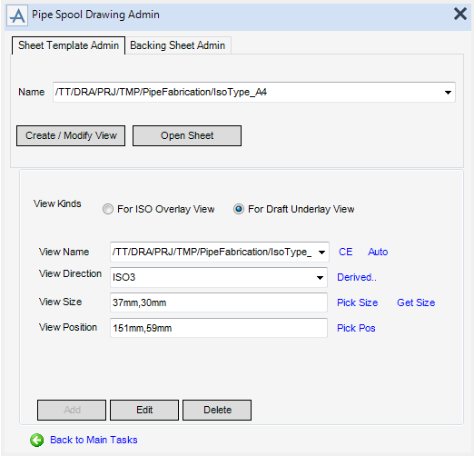
Select the Draft Underlay View radio button to display the model using a specified view direction.
|
Alternatively, click CE to populate the field from the currently selected VIEW element in the Draw Explorer.
Alternatively, click Auto to create a new view that is automatically named using the properties of the currently selected SHEET element in the Draw Explorer.
|
|
|
Alternatively, click Derived to set the view orientation from an existing view.
|
|
|
Input values to define the display area for the underlay view. For example input a value of 37,30 to define a view 37mm wide by 30mm high.
Click Pick Size to define an area for the underlay view using two picked points on the drawing canvas.
Click Get Size to define an area for the underlay view using an existing view.
|
|
|
Click Pick Pos to define the centre position of the underlay view using a picked point on the drawing canvas.
|
|
|
Click to return to the Pipe Spool Drawing Admin window main tasks.
|

