DRAW Administrator Guide
Area Based Automatic Drawing Production : Create and Modify Template Drawings : Create and Modify Keyplan Layers
There are two methods of creating a keyplan within ABA.The first is the View Based Method method and the second is the Overlay Sheet Method.
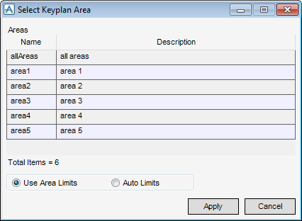
The Select Keyplan Area window lists all area projects that have been setup using the Area Definition window. Refer to Create and Modify Areas for further information.
Select the Use Area Limits option button to use the selected area for the keyplan and set the view scale so that the limits box for the area fits into the view frame for the keyplan.
Select the Auto Limits option button for a view scale to be automatically calculated so that the contents of the drawlist for the keyplan view fit into the view frame.
Click Apply to confirm the keyplan area settings or Cancel to discard any changes and close the Select Keyplan Area window.
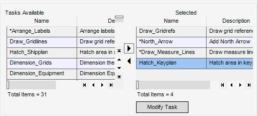
On the ABA Template View window, add the user task Hatch_Keyplan to the Selected window. Refer to Create and Modify ABA Template View for further information.
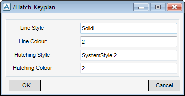
To set the Hatching and Frame styles and colours, click Modify Task to display the
/Hatch_Keyplan window.
/Hatch_Keyplan window.
Input a line style for the frame in the Line Style field.
Input a value for the frame colour in the Line Colour field.
Input a value for the hatching style in the Hatching Style field.
Input a value for the hatching colour in the Hatching Colour field.
Click OK to set the hatching and frame styles or Cancel to discard any changes and close the /Hatch_Keyplan window.
On the ABA Template View window, add the user task /*Keyplan_View to the Selected list. Refer to Create and Modify ABA Template View for further information.
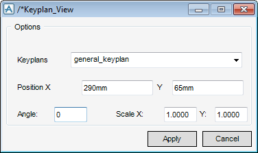
Select /*Keyplan_View in the Selected list and click Modify Task to display the /*Keyplan_View window.
The /*Keyplan_View window allows you to modify the Keyplan position and scale options.
Select a Keyplan from the drop-down list.
Input values in the Position X and Y fields to specify the location of the bottom left corner of the Overlay sheet to fit onto the drawing template.
Input a value for the angle in the Angle field.
Click Apply to modify the Keyplan View settings or Cancel to discard any changes and close the /*Keyplan_View window.
The Add Hatched Areas to an Overlay window is used to create a representation of each of the areas in the 3D model. It allows you to automatically create a set of boxes with shading to represent each area.
Make sure Name has been set to the correct overlay. If not, click CE and navigate to the required overlay.
Set the Frame colour and style and Hatch Pattern colour and style for the hatching layers in the Select Hatching Pens part of the window. Select Hatching Pens has similar functionality to the Pens tab of the Library Attributes window. Refer to Library for further information.
The Select Text Attributes part of the window allows you to modify the text properties for the hatching layers.
Input the required text into the Text field.
Input a value for the position of the text in the Position X and Y fields. Alternatively, click Cursor to identify the position of the text on the drawing canvas. The Point Construction Option Form displays. Refer to Define View Frame with Cursor for further information.
Select from the Colour drop-down list to define the colour for the text. Alternatively, click Pick to display the Pick a Colour window. Refer to Colour for further information.
Select from the Font drop-down list to define a font for the text.
Input a value in the Height field to define the height of the text.
Select a direction from the Direction drop-down list to define the Keyplan View Direction. The hashed areas are built orthogonal to the selected View direction.
Each layer represents a particular area of the 3D model as defined in the Area Definition window. When the drawing is processed with this keyplan applied, the only visible keyplan layer is the area for which the drawing is using.
Click Apply to modify the properties for the hatching layers or Cancel to discard any changes and close the Add Hatched Areas to an Overlay window.
On the ABA Template Sheet window, add the task *Keyplan_View to the Selected list. Refer to Create ABA Template Sheet for further information.


