DRAW Administrator Guide
Isometric Automatic Drawing Production : Configuration : Defaults
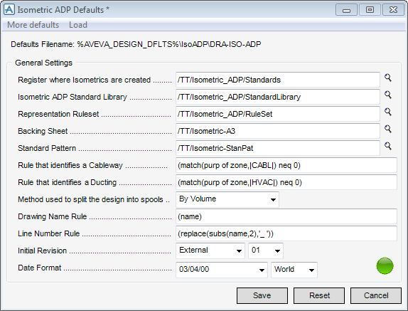
The Isometric ADP Defaults window displays the Isometric ADP Defaults from the supplied file named DRA-ISO-ADP. It displays the hierarchy required for running IsoADP and the essential data needed for HVAC standard drawing.
All of the administrator tasks that are associated with the modification of defaults are initiated from the Isometric ADP Defaults window which acts as a task hub.
Depending on selections made in the Isometric ADP Defaults window, you are presented with further windows prompting for input.
To load HVAC standard drawings, click Load and select Standard Drawings from the drop-down list. Refer to HVAC Standard Drawings for further information.
To modify specific defaults, click More Defaults. Refer to Specific Defaults for further information.
The General Settings part of the Isometric ADP Defaults window, allows you to modify Isometric ADP Defaults.
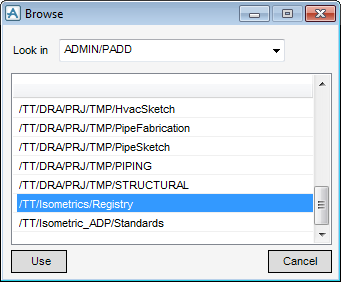
The Browse window is populated with the available registries by database.
From the Look in drop-down menu, select the required database.
Click Use to select the new registry or click Cancel to discard any changes and close the Browse window.
You can select a library as required. Click the magnifying glass adjacent to the current library to display a Browse window.
From the Look in drop-down menu, select the required library.
You can select a Representation Ruleset as required. Click the magnifying glass adjacent to the current Ruleset to display a Browse window.
From the Look in drop-down menu, select the required Ruleset.
You can select a Backing Sheet as required. Click the magnifying glass adjacent to the current Backing Sheet to display the Browse window.
From the Look in drop-down menu, select the required Backing Sheet.
Click Use to select the Backing Sheet or click Cancel to discard any changes and close the Browse window.
IsoADP can create a Standard Pattern on each sheet. The Overlay (OVER), is positioned on the sheet as defined by the Backing Sheet. Refer to Standard Pattern for further information.
You can select a Standard Pattern as required. Click the magnifying glass adjacent to the current Standard Pattern to display the Browse window.
From the Look in drop-down menu, select the required Standard Pattern.
Click Use to select the Standard Pattern or click Cancel to discard any changes and close the Browse window.
Displays the AVEVA E3D™ rule that is used to find the Electrical Cable Tray (CWAY) elements for detailing. The default (match(func of zone,|Cable Way|) neq 0) only searches in those ZONEs that have their attribute Function set to Cableway.
Input the new rule in the Rule that identifies a Cable Tray field.
Displays the AVEVA E3D™ rule that is used to find the HVAC elements for detailing. The default (match(purp of zone,|HVAC|) neq 0) only searches in those ZONEs that have their attribute Function set to HVAC.
Input the new rule in the Rule that identifies a Ducting field.
Allows you to choose the method of splitting HVAC or CWAY branches into Fabrication Spools. From the drop-down menu select By Volume or Split Point.
Input the new rule in the Drawing Name Rule field.
Displays the AVEVA E3D™ rule that is used to extract the Line Number from the relevant drawing elements HVAC or CWAY, and is used on the default Backing Sheet in Title Block The rule can be used within any Continuation Labels on the isometric view.
The default (replace(subs(name,2),'_',' ') uses the NAME of the HVAC or CWAY and replaces any underscore '_' characters with a blank space. The line number is stored in the UDA :IdpLineNo at the DRWG element.
Input the new rule in the Line Number Rule field.
Allows you to set the Date format for the drawings; from the drop-down menu, select the date format and then select World or USA to determine the order of the day and month to suit World standards or North American standards.
Click Reset to revert to the settings applied when the Isometric ADP Defaults window was opened. A Confirm window displays asking you to OK the cancellation of changes. Click Yes to discard the changes.
Click Save to apply the Isometric ADP defaults. A Confirm window displays asking you to OK the changes. Click Yes to save the changes. Click Close to close the Isometric ADP Defaults window.
Click Cancel to discard any changes and close the Isometric ADP Defaults window. A Confirm window displays asking you to OK the cancellation. Click No to discard any changes and close the Isometric ADP Defaults window.
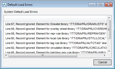
On the Isometric ADP Defaults window, click  , to display the Default Load Errors window, listing the elements that do not exist.
$m %PMLLIB%\isometricadp\data\Metric_Library_load.dat 5 ENU TT/
$m %PMLLIB%\isometricadp\data\Imperial_Library_load.dat 6 XYZ TT/
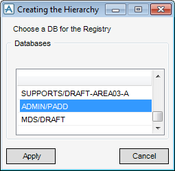
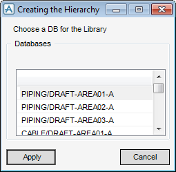
On the Isometric ADP Defaults window, click  to display the Creating the Hierarchy window, listing all writable PADD databases.
Click Apply to create the new DEPT and REGI elements or click Cancel to discard any changes and close the Creating the Hierarchy window.
The new DEPT and REGI elements are created in the Creating the Hierarchy window, you are prompted to Load the Isometric ADP Library
Click Apply to create the Isometric ADP Library or click Cancel to discard any changes and close the Creating the Hierarchy window.
IsoADP must now be configured. Refer to Specific Defaults for further information on configuration.
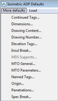
Specific defaults allow you to configure components of an IsoADP deliverable. On the Isometric ADP Defaults window, click More Defaults to display the More Defaults drop-down list:
|
•
|
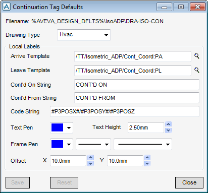
There are separate settings for each drawing type. From the Drawing Type drop-down menu, select HVAC or Electrical.
The Symbolic Template to be used at the start point of the spool must be set. Input the required name into the Arrive Template field or click the magnifying glass adjacent to the Arrive Template field to display the Browse window.
The Browse window is populated with the available registries by database. From the Look in drop-down menu, select the required database.
Click Use to select the new registry or click Cancel to discard any changes and close the Browse window.
The Symbolic Template used at the end point of the spool must now be set. Input the required name into the Leave Template field or click the magnifying glass adjacent to the Leave Template field to display the Browse window.
The Browse window is populated with the available registries by database. From the Look in drop-down menu, select the required database.
Click Use to select the new registry or click Cancel to discard any changes and close the Browse window.
Input the text required for the ON label in the Cont’d On String field.
Input the text for the From Label in the Cont’d From String field.
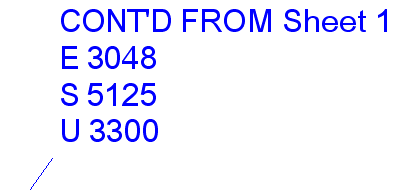
To set the drafting intelligent hash code string that extracts the continuation tag values from the 3D model database, input the hash code in the Code String field.
Select a colour from the Text Pen drop-down menu, to display in the chosen template. The label attribute is set to TXCOLOUR.
Select the character height from the Text Height drop-down menu, to display in the chosen template.
Select a colour for the frame and leader-lines from the Frame Pen drop-down menu, then select a line thickness and style from the drop-down menus. The label attributes are set to LLCOLOUR, LLSTYLE and LFSTYLE.
Select a default Offset position from the Label connection at the element by selecting X and Y coordinates. The Label attribute is set to XYPO.
Click Reset to revert to the settings applied when the Continuation Tag Defaults window was opened. A Confirm window displays asking you to OK the cancellation of changes. Click Yes to discard the changes.
Click Save to apply the continuation tag defaults. A Confirm window displays asking you to OK the changes. Click Yes to save the changes. Click Close to close the Continuation Tag Defaults window.
Click Cancel to discard any changes and close the Continuation Tag Defaults window. A Confirm window displays asking you to OK the cancellation. Click No to discard any changes and close the Isometric Continuation Tag Defaults window.
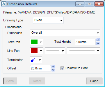
There are separate settings for each drawing type, select HVAC or Electrical, from the Drawing Type drop-down list.
Select a colour for the text from the Text Pen drop-down menu, the dimension attribute is now set to DTCOLOUR.
Input a height in the Text Height field, the dimension attribute is set to DTCH.
Select a colour for the dimension and projection lines from the Line Pen drop-down menu, then select a style and line thickness from the drop-down menus. The dimension attributes are now set to DLCOLOUR, PLCOLOUR, DLSTYLE and PLSTYLE.
Select the terminator style from the Terminator drop-down menu.
A dimension offset position must now be set, the default position of 25.0mm displays. However, this can be repositioned, select a position from the Offset drop-down menu. The dimension attribute is now set to DOFF.
To relate the dimension offset position to the actual bore of the component being dimensioned, select the Relative to Bore check box. The dimension is now incremented to suit as the bore increases or decreases.
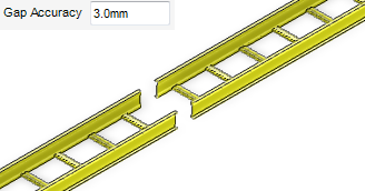
For a CWAY drawing, you can specify the size of the gap between components that are dimensioned. Input the size of the gap in the Gap Accuracy field. Any gaps that are smaller than the specified size are ignored.
Click Reset to revert to the settings applied when the Dimension Defaults window was opened. A Confirm window displays asking you to OK the cancellation of changes. Click Yes to discard the changes.
Click Save to apply the dimension defaults. A Confirm window displays asking you to OK the changes. Click Yes to save the changes. Click Close to close the Dimension Defaults window.
Click Cancel to discard any changes and close the Dimension Defaults window. A Confirm window displays asking you to OK the cancellation. Click No to discard any changes and close the Dimension Defaults window.
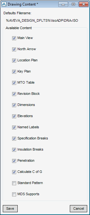
Any of the components in the Drawing Content window, can be added to the Isometric drawing, select the relevant check box.
Click Save to apply the drawing content defaults. A Confirm window displays asking you to OK the changes. Click Yes to save the changes. Click Close to close the Drawing Content window.
Click Cancel to discard any changes and close the Drawing Content window. A Confirm window displays asking you to OK the cancellation. Click No to discard any changes and close the Drawing Content window.
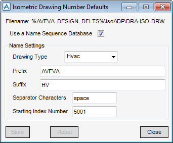
The Drawing Number is calculated using the PML Function !!isoDrwgNo ().
Refer to User PML Functions for further information on PML Functions.
To use the Name Sequence Database (NSEQ) method for extracting the next index number, select the Use a Name Sequence Database check box. Refer to Name Sequence Database for further information.
|
Note:
|
The Starting Index Number for the chosen Drawing Type must be input, use numbers with leading zeros, for example, 0001. Input the required number in the Starting Index Number field.
Click Reset to revert to the settings applied when the Isometric Drawing Number Defaults window was opened. A Confirm window displays asking you to OK the cancellation of changes. Click Yes to discard the changes.
Click Save to apply the drawing number defaults. A Confirm window displays asking you to OK the changes. Click Yes to save the changes. Click Close to close the Isometric Drawing Number Defaults window.
Click Cancel to discard any changes and close the Isometric Drawing Number Defaults window. A Confirm window displays asking you to OK the cancellation. Click No to discard any changes and close the Isometric Drawing Number Defaults window.
Select Drawing Type from the Drawing Type drop-down menu. There are some differences between the options available for HVAC or Electrical, so each drawing type is described individually.
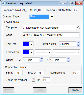
Select HVAC from the Drawing Type drop-down list to display the HVAC version of the Elevation Tag Defaults window.
Input the required name in the Template field or click the magnifying glass adjacent to the Template field to display the Browse window.
The Browse window is populated with the available registries by database. From the Look in drop-down menu, select the required database. You must now select the registry that is used to hold the drawing.
Click Use to select the new registry or click Cancel to discard any changes and close the Browse window.
IsoADP replaces the word P3 in the hash code string with the relevant P‑point number specified in the Connection Points part of the window. Consequently P3 must always be included in any hash code string, if the correct value is to appear in the label.
From the Text Pen drop-down menu, select a colour for the Text that appears in the selected template. The Label attribute is set to TXCOLOUR.
From the Text Height drop-down menu, select a character height for Text that appears in the selected template.The Label attribute is set to CHEI.
A colour, line thickness and line style for the Frame and the Leader-line must now be selected. Select a colour from the Frame Pen drop-down menu and a line thickness and style. The Label attributes are set to LLCOLOUR, LFCOLOUR, LLSTYLE and LFSTYLE.
Input the coordinates in the Offset fields. The label attribute is set to XYPO.
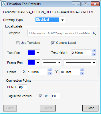
To tag a component that appears in a vertical leg, select the Tag in the vertical check box. The Ppoint used to tag these components can be changed by setting the value that appears in the on field.
Click Reset to revert to the settings applied when the Elevation Tag Defaults window was opened. A Confirm window displays asking you to OK the cancellation of changes. Click Yes to discard the changes.
Click Save to apply the elevation tag defaults. A Confirm window displays asking you to OK the changes. Click Yes to save the changes. Click Close to close the Elevation Tag Defaults window.
Click Cancel to discard any changes and close the Elevation Tag Defaults window. A Confirm window displays asking you to OK the cancellation. Click No to discard any changes and close the Elevation Tag Defaults window.
Select Electrical from the Drawing Type drop-down list to display the electrical version of the Elevation Tag Defaults window.
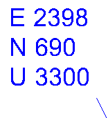
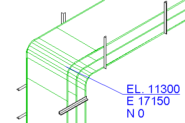
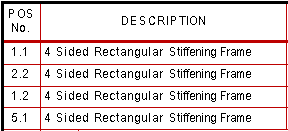
The method uses the PML Function !!isoCwayElev() and produces the following result for both multi-level and single level Cableways:
The method uses the User PML Function !!isoUserCwayElev(), which evaluates all levels and produces the following result for multi-level on the left and single level Cableways on the right:
Refer to User PML Functions for further information on PML Functions.
Select whether to use a Symbolic Template or a General Label for tagging by the selection of the relevant Use Template or General Label check boxes.
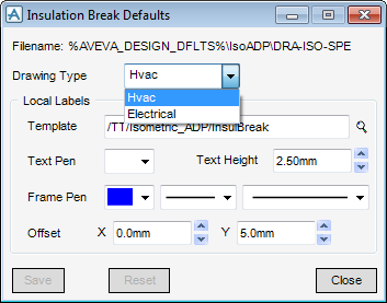
The functionality available from the Insulation Break Defaults window is identical to that available from the Elevation Tag Defaults window. Refer to Elevation Tags for further information.
Click Reset to revert to the settings applied when the Insulation Break Defaults window was opened. A Confirm window displays asking you to OK the cancellation of changes. Click Yes to discard the changes.
Click Save to apply the Insulation Break defaults. A Confirm window displays asking you to OK the changes. Click Yes to save the changes. Click Close to close the Insulation Break Defaults window.
Click Cancel to discard any changes and close the Insulation Break Defaults window. A Confirm window displays asking you to OK the cancellation. Click No to discard any changes and close the Insulation Break Defaults window.
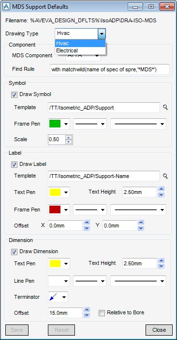
Select a Drawing Type from the drop-down list.
The Component part of the MDS Support Defaults window provides the information required to collect the support locations in the HVAC or CWAY main.
From the MDS Component drop-down menu, select the element type used to represent the support location
The Symbol part of the MDS Support Defaults window allows you to select and modify the symbol used at support locations.
Select the Draw Symbol check box to create a symbol at each support location, then set the Symbolic Template to be used.
Input the required name in the Template field or click the magnifying glass adjacent to the Template field to display the Browse window.
The Browse window is populated with the available registries by database. From the Look in drop-down menu, select the required database.
Click Use to select the new registry or click Cancel to discard any changes and close the Browse window.
Select a colour, line thickness and line style from the Frame Pen and leader-line drop-down lists.
The label attributes are set to LLCOLOUR, LFCOLOUR, LLSTYLE and LFSTYLE from the Frame Pen style and line thickness drop-down menus.
Set a scale in the Scale field, the label attribute is set to XYSC.
The Label part of the MDS Support Defaults window allows you to select and modify the label used at support locations.
Select the Draw Label check box to create a label at each support location.
Input the required name in the Template field or click the magnifying glass adjacent to the Template field to display the Browse window.
The Browse window is populated with the available registries by database. From the Look in drop-down menu, select the required database.
Click Use to select the new registry or Cancel to discard any changes and close the Browse window. The label attribute is set to XYPO.
The text functionality of the of the MDS Support Defaults window is identical to that available from the Elevation Tag Defaults window. Refer to Elevation Tags for further information.
The Dimension part of the MDS Support Defaults window allows you to select and modify dimension settings for the support location.
Select the Draw Dimension check box to create a dimension at each support location.
The functionality available from the Dimension part of the MDS Support Defaults window is similar to that available from the Dimension Defaults window. Refer to Dimensions for further information. The Dimension part of the MDS Support Defaults window differs from the Dimension window in that it does not have the Drawing Type and Dimension drop-down lists.
Click Reset to revert to the settings applied when the MDS Support Defaults window was opened. A Confirm window displays asking you to OK the cancellation of changes. Click Yes to discard the changes.
Click Save to apply the MDS support defaults. A Confirm window displays asking you to OK the changes. Click Yes to save the changes. Click Close to close the MDS Support Defaults window.
Click Cancel to discard any changes and close the MDS Support Defaults window. A Confirm window displays asking you to OK the cancellation. Click No to discard any changes and close the MDS Support Defaults window.
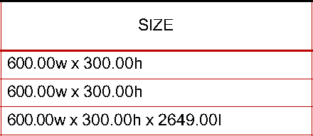
The MTO Table displays information about the components of the drawn spool. The table is fully configurable by changing the defaults and manipulating the symbolic templates and associated PML functions used to build it. Refer to Material Take-Off Table for further information.
|
•
|
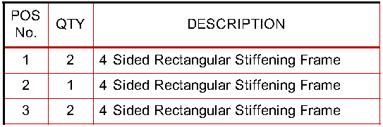
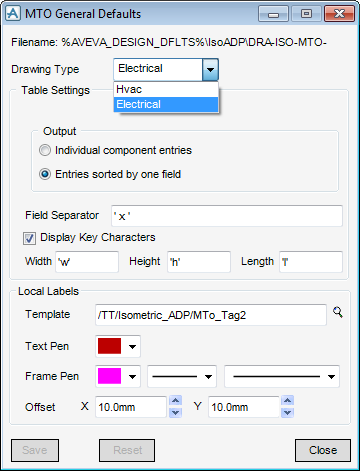
Select the Individual component entries option button so that in an individual table, each component has its own entry in the table and is given a Position Number extracted from the database. However this can result in very long tables.
Select the Entries sorted by one field option button so that in a sorted table, all components that have the same description and parameter values are grouped together and display with a Position Number and quantity.
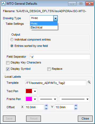
Select HVAC from the Drawing Type drop-down list to display the HVAC version of the MTO General Defaults window.
The character that is used to separate the parameter values from one another, must be set. Any character for this separator including a blank can be used, input a value in the Field Separator field.
To display the Key characters, select the Display Key Characters check box.
The Parameter KEY character is used to relate the Parameter to the HVAC Standard Drawings for each component. Refer to HVAC Standard Drawings for further information.
To display a symbol alongside each parameter if set, select the Display Symbol check box.
To replace the KEY character with any existing SYMBOL select the Replace check box.
Both the KEY and SYMBOL characters are stored in data sets in the Catalogue under the section /CADCHVACMTO, which is loaded during the Project Set Up process via the supplied data file Hvac_Paragon.dat. Refer to Project Set-up for further information.
Select Electrical from the Drawing Type drop-down list to display the Electrical version of the MTO General Defaults window.
To display the Key characters, select the Display Key Characters check box.
The character that is used to separate the parameter values from one another, must now be set. Input a value in the Field Separator field.
The Parameter KEY character is used to relate the Parameter to the HVAC Standard Drawings for each component. Refer to HVAC Standard Drawings for further information.
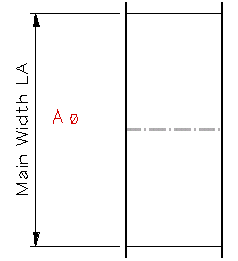
To set the character for each size parameter, type the relevant values into the Width, Height and Length fields.
To set the Symbolic Template to be used, input the required name directly into the Template field or click the magnifying glass adjacent to the Template field to display the Browse window.
The Browse window is populated with the available registries by database. From the Look in drop-down menu, select the required database.
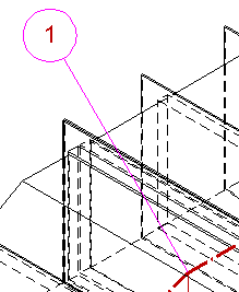
The functionality available from the Local Labels part of the MTO General Defaults window is similar to functionality available in the Electrical version of the Elevation Tag Defaults window. The Local Labels part differs from the Elevation Tag Defaults window in that it does not have the Use Table and General Template check boxes or the Text Height field. Refer to Elevation Tags for further information.
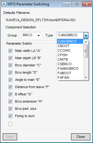
To make it easier to select the component one by one, they are placed into Groups. From the Group drop-down menu, select the compliant group type.
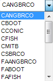
From the Type drop-down menu, select the component type from the list of available components.
To specify the display of parameter switches, on the Parameter Switch part of the MTO Parameter Switching window, select the required check box.
Click Save to apply the parameter switching defaults and then Close to close the MTO Parameter Switching window.
Click Cancel to discard any changes and close the MTO Parameter Switching window. A Confirm window displays asking you to OK the cancellation. Click No to discard any changes and close the MTO Parameter Switching window.
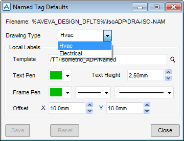
Select a Drawing Type from the drop-down list.
The functionality available from the Names Tag Defaults window is similar to that available from the Elevation Tag Defaults window. The Names Tag Defaults window differs from the Elevation Tag Defaults window in that it does not have a Connection Points part, Code field, Use Template or General Label text boxes. Refer to Elevation Tags for further information.
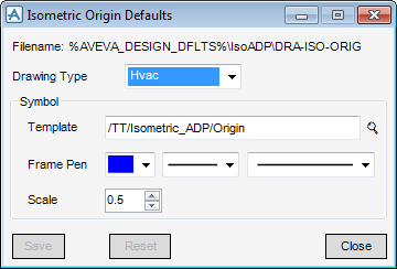
Select a Drawing Type from the drop-down list.
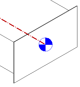
The functionality available from the Isometric Origin Defaults window is similar to that available from the Symbol part of MDS Support Defaults window. The Isometric Origin Defaults window differs from the MDS Support Defaults window in that it does have a Draw Symbol check box. Refer to Supports for further information.
Select a Drawing Type from the drop-down list.
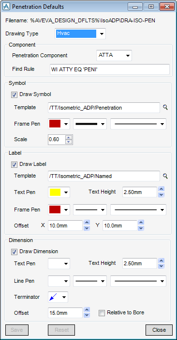
Select the Penetration from the Penetration Component drop-down menus.
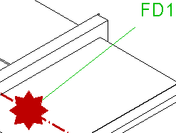
The functionality available in the Penetrations window is similar to that available in the MDS Support Defaults window. Refer to Supports for further information.
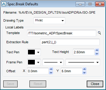
Select a Drawing Type from the drop-down list.
Input an extraction rule in the Extraction Rule field to extract a string from the name of the HVAC or CWAY specification.
The functionality of the Local Labels part of the Specification Break Defaults window is similar to that of the Local Labels part of the Elevation Tag Defaults window. The Specification Breaks Default window differs from the Elevation Tag Defaults window in that it does not have a Code field, Use Template and General Label check boxes. Refer to Elevation Tags for further information.
The top part of the Output section indicates that a MS Excel report of the Bill of Materials is generated by default to the specified directory. If the report is not required the True value can be modified to False.
The bottom part of the Output section indicates that a PDF of the isometric is generated by default to the specified directory. If the PDF is not required the True value can be modified to False.
There are two methods to automatically set Drawing Numbers for each Isometric drawing. Refer to Drawing Number for further information.
The first line contains the format of the drawing number. The word REPLACE is mandatory and is replaced by the series number.

