DRAW Administrator Guide
Style Library : Create Style Library
Click OK to display the Style Library window or Cancel to discard any changes and close the Create RPLB window.
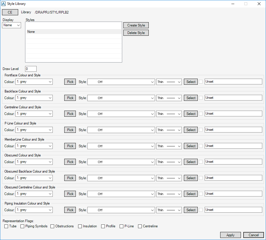
The upper part of the Style Library window displays the name of the current RPLB that is being used as a Style Library, and a list of all STYLs within it.
|
Note:
|
None displays in the Styles list if you have just created the RPLB.
|
Click OK to add the name to the list or Cancel to discard any changes and close the Create STYL window.
The created STYL is highlighted as the current selection. The STYL default attribute settings display in the lower part of the Style Library window.
The amount of information that displays in the Styles list is controlled by the option selected from the Display drop-down list:
You can set an appropriate Display mode to make it easier to find the STYL whose attributes are to be modified.
The Draw Level text box displays the Drawing Level (DLEV) setting. The attribute restricts the display of elements using this Style to just those that include this number in their drawing level range, as set in MODEL.
Standard options of line colour and style are set explicitly by selecting system-defined settings from the colour, line-pattern and thickness drop-down lists. To select a colour from a colour palette, click Pick to display the Pick a Colour window. The functionality of the Pick a Colour window is explained. Refer to Colour for further information.
To select a user-defined style, click Select to display, the User-defined styles window. A style table is selected and then a selection is made from the list of styles. After selecting a user defined style the check box displays a tick. You can de-select this check box to use a system defined style. The functionality of the User-defined linear styles window is explained. Refer to User-Defined Linear Styles for further information.
The Representation Flags display the current On/Off settings for the Tube (TUBE), Piping Symbols (PSYM), Obstructions (OBST), Insulation (INSU), Profile (PRFG), P-Line (PLFG) and Centreline (CLFG) flags:
Click Apply to define the style library settings or Cancel to discard any changes and close the Style Library window.


