Catalogues and Specifications
User Guide
Piping : Specific piping hierarchy
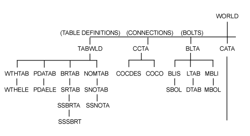
These tables are a collection of similar elements in the database which the administrator can group together elements to help with creation of specifications such as bore ranges, branch and reducer types, wall thickness and pipe data. Refer to Wall Thickness Table, Pipe Data Table, Create Branch Tables and Create Nominal Bore World for further information. On all windows, click Apply or OK to save the changes or click Cancel to discard any inputs and close the window.
The Connection Compatibility Table hierarchy holds a list of all the compatible connection types for Piping Components in a set project. Refer to Coco Table for further information.
The Bolt Table hierarchy contains information describing the nature of the bolted connections of Piping Components in a project. Refer to Bolt Diameter and Length Tables for further information.
Many multi-purpose windows provide similar functionality through the create and modify options. Refer to Multi-Purpose Windows for further information.
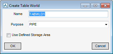
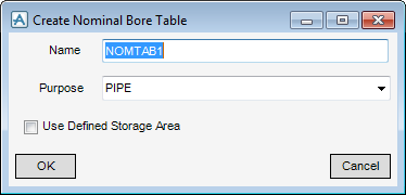
A Nominal Bore Table (NOMTAB) element is the administrative element for a nominal bore table and must be created below a Table World (TABWLD) element.
|
Note:
|
The Nominal Bore Table does not provide wall thickness data in the model, refer to Wall Thickness Table for further information.
|
|
Note:
|
Many multi-purpose windows provide similar functionality through the create and modify options, the functionality is common throughout all disciplines. Refer to Multi-Purpose Windows for further information.
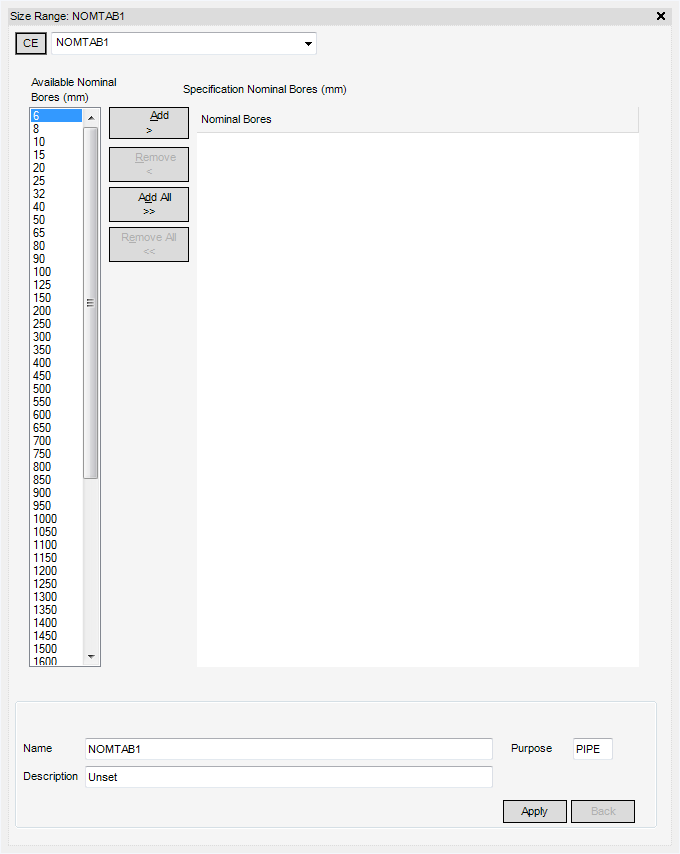
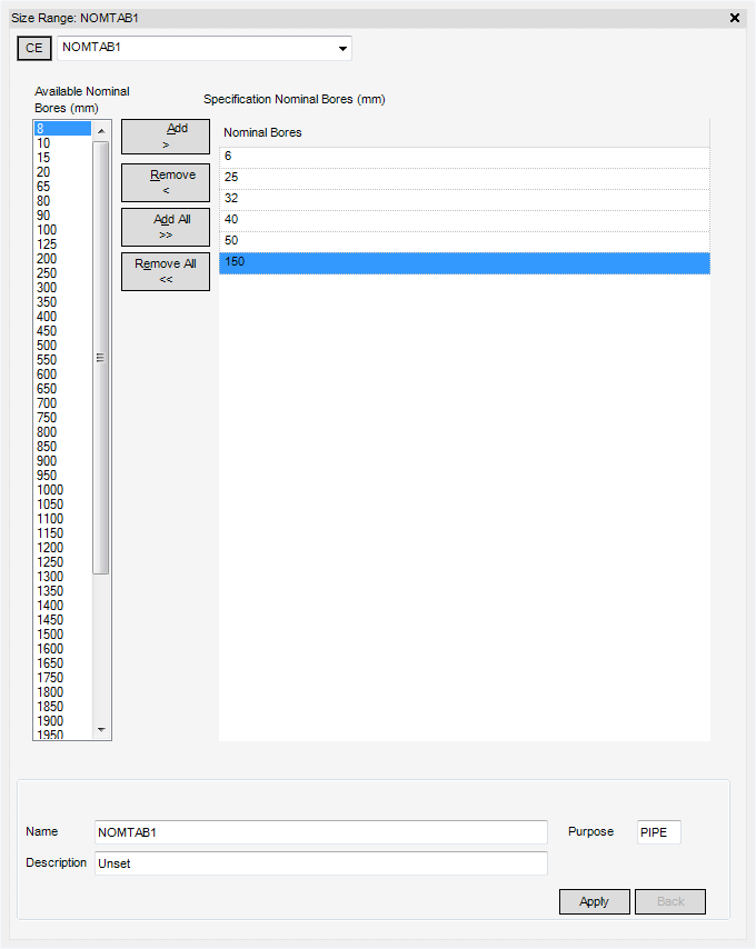
Once the administrative elements have been created, the Size Range window is displayed. By default, the Name fields are automatically populated, the Description is Unset and the Purpose is set to PIPE, as the currently active discipline is PIPING.
Click to highlight the desired bore sizes in the Available Nominal Bores (mm) list. Multiple bores can be selected at once by left clicking and dragging the mouse pointer. To remove particular highlighted entries hold down the CTRL key and left click on a bore size.
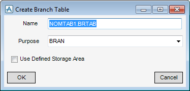
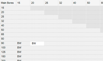
Branch tables are used as a way of selecting the type of fitting used for example BW could indicate a Butt Weld Tee, SW a Socket Weld Tee, WOL a Butt Weld Outlet Boss and SOL a Socket Weld Outlet Boss. A Branch Table (BRTAB) element must be created below a Table World (TABWLD) element.
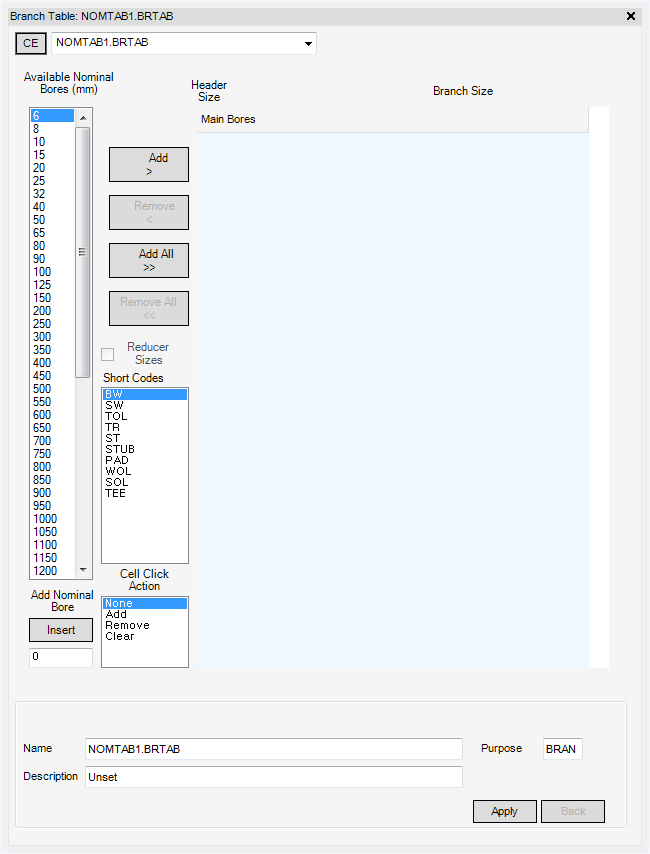
Many multi-purpose windows provide similar functionality through the create and modify options, the functionality is common throughout all disciplines. Refer to Multi-Purpose Windows for further information. Once the Branch element (BRTAB) is created, the Branch Table window is displayed.
By default, the name fields are automatically populated, the description is Unset and the Purpose is set to BRAN, as the currently active discipline is PIPING.
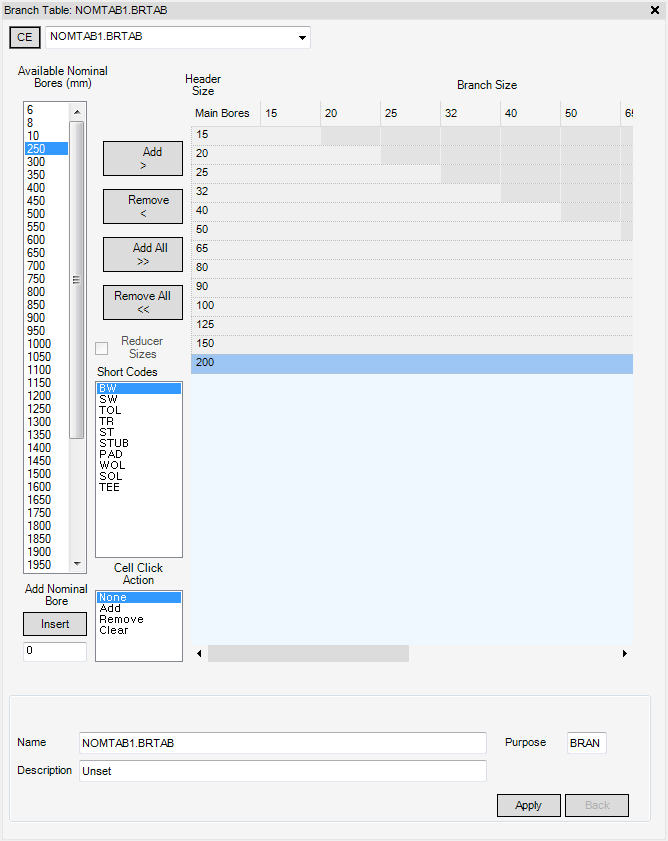
Click to highlight the desired bores in the Available Nominal Bores (mm) list by left clicking on the desired bore size. Multiple bores can be selected at once by left clicking and dragging the mouse pointer down the list.
Once the desired bores have been added to the Branch Table, short codes can be added. From the Cell Click Action part of the Branch Table, click Add.
In the Main Bores part of the Branch Table window, click on the required empty cells to add the short code.
To remove short codes, from the Cell Click Action part of the Branch Table window, select Clear and left click on the cell within the Branch Table.
To return the mouse pointer to normal operation, from the Cell Click Action part of the Branch Table window, select None.
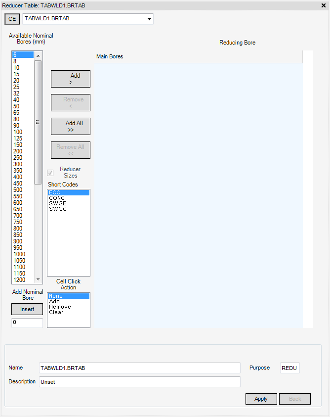
The Reducer Sizes check box is only active when used in conjunction with the Specification creation windows. When a Spec is associated with a Specification Table this check box allows the quick switching between windows allowing faster edits to be made.
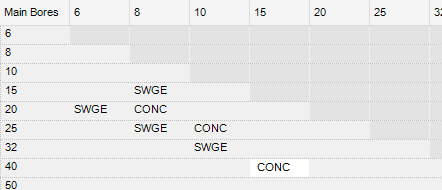
The Reducer Table creation window behaves in exactly the same manner as the Branch Table window. To avoid repetition this section only lists the differences between the two. A Reducer Table must be created below a Table World (TABWLD) element.
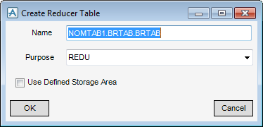
Many multi-purpose windows provide similar functionality through the create and modify options, the functionality is common throughout all disciplines. Refer to Multi-Purpose Windows for further information. Once the Reducer Table (BRTAB) element, the Reducer Table window is displayed.
By default, the name fields are automatically populated, the description is Unset and the Purpose is set to REDU, as Reducer has been selected from the Create Specification Table group.
The only difference in behaviour to the Branch Table window is the list of Short Codes available for selection, by default, these are:
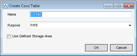
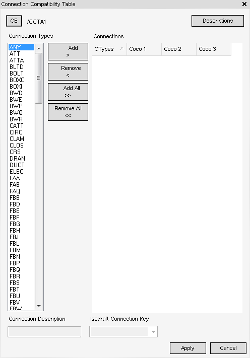
Many multi-purpose windows provide similar functionality through the create and modify options, the functionality is common throughout all disciplines. Refer to Multi-Purpose Windows for further information. Once the Coco table element is created, the Connection Compatibility Table window is displayed.
|
Note:
|
If the connection compatibility table is from a read-only Master project, an error message is displayed. The table is displayed and the data in the Connections grid is readable but the table will be in read-only mode.
|
From the Connection Types part of the Connection Compatibility Table window, select the required connection types from the list of available connections. Multiply selections can be made by holding down the CTRL key and using the left click on the mouse.
From the Connection Types part of the Connection Compatibility Table window, click to highlighted a connection type to the Connections grid then by click Add >.
|
Note:
|
When a connection type is added from the Connections Types list to the Connections grid, it is removed from the Connections Types list and vice versa.
|
|
Adds all of the highlighted connection type to the Connections part of the Connection Compatibility Table.
|
|
|
Removes the highlighted connection type to the Connections part of the Connection Compatibility Table.
|
|
|
Remove all of the highlighted connection type to the Connections part of the Connection Compatibility Table.
|
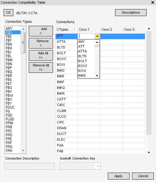
Click an empty cell in the Connections grid to display a drop-down list of connection types (Coco). Modifications to existing Connection Compatibility configuration can be made by selecting a new value or deleting the configuration currently present to remove it.
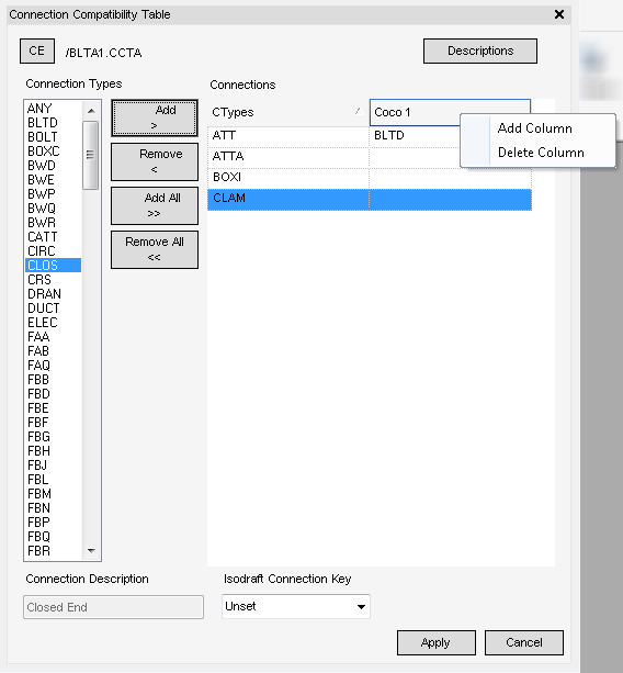
If additional Coco columns are required in the Connections grid, right click in the Connections table header to display the following options:
From the displayed pop up menu, click Add Column to insert an additional column to the Connections grid.
To remove a Coco column, click the column heading to make it active then right click, from the displayed pop up menu, select Delete Column to remove the column from the Connections grid, the Confirm Column Deletion window is displayed, prompting for confirmation of the action:
To add a description to a CType displayed in the Connections grid of the Connections Compatibility Table window.
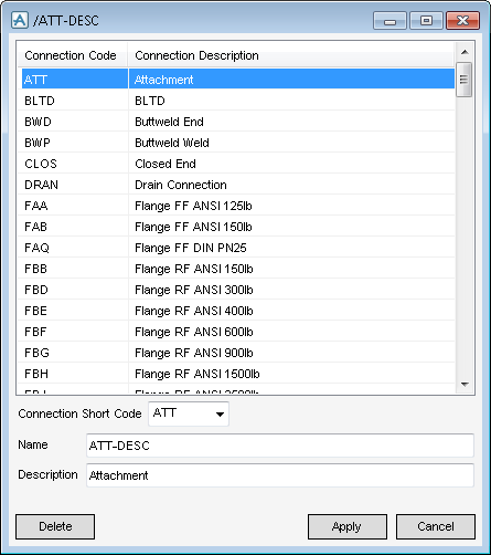
From the Connections Compatibility Table window, click Descriptions to display the /XXX-DESC window. The XXX-DESC window is populated with supplied standard connections and descriptions.
The ISODRAFT Connection Key (CKEY) attribute is used by ISODRAFT to determine what type of connection is used to join two elements (for example: Butt weld, Screwed and so on). Refer the Connection Compatibility Tables for further information, to edit the CKey refer to Keys for further information.
Once an entry has been populated in the Connections grid, the ISODRAFT Connection Key drop-down, located at the bottom of the Connections Compatibility Table window, becomes active. By default Unset is selected, if this is left as the default it is assumed to be plain connection.
|
•
|
BW for butt weld
|
|
•
|
CP for compression
|
|
•
|
FL for flange
|
|
•
|
PL for plain
|
|
•
|
SC for screwed
|
|
•
|
SW for socket weld
|
|
•
|

