Catalogues and Specifications
User Guide
Supports
: Modify User Defined Ancillary Geometry
Modify User Defined Ancillary Geometry
The Supports application allows you to create a set of ancillary standards with their own geometry. Configuration of standards dimensionally is covered in
Ancillary Data
.
The user defined ancillary standards comprise a number of support types. The table displays the user defined ancillary types that have been created that can be configured geometrically:
Standard
Description
Range
Total
From
To
AT
Ancillary
AT500
AT700
201
LT
Lug
LT500
LT700
201
BT
U-Bolt
BT500
BT700
201
AN
Anchor for shoes
AN500
AN569
70
AN
Anchor for pipes
AN570
AN639
70
AN
Anchor for trunnions
AN640
GT700
61
GT
Guide for shoes
GT500
GT569
70
GT
Guide for pipes
GT570
GT639
70
GT
Guide for trunnions
GT640
GT700
61
ST
Stops for shoes
ST500
ST569
70
ST
Stops for pipes
ST570
ST639
70
ST
Stops for trunnions
ST640
ST700
61
AC
Ancillary Components for Trunnions
AC500
AC599
100
AC
Plate Component for Trunnions
AC600
AC700
101
CA
Cable Tray Ancillaries
CA500
CA700
201
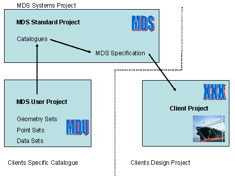
The ability to create the user defined ancillary types is achieved by supports being configured to use a blank set of ancillaries, so that users can complete their own geometry. A user project called MDU is created; a hierarchy /MDU prefix is used instead of the /MDS prefix where applicable. The example displays how this is implemented into a supports project environment.
The MDU project has the geometry and point sets pre-created and linked into the MDS catalogue and specification. The geometry sets are empty and the point sets have the minimum p-point requirements. You can then create the geometry within the MDU project and set up any design parameters required for the component. The MDU project only stores geometry, point and data sets for the types and ranges detailed earlier.
1974 to current year.
AVEVA Solutions Limited and its subsidiaries. All rights reserved.