Catalogues and Specifications
Reference Manual
Catalogue Database Elements Setup in PARAGON : Structural Pointsets (PTSSET)
|
Figure 7:1.
|
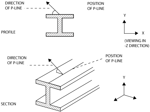
A P-line is the structural counterpart of a P-point. It is a line which runs the full length of a Component parallel to its Z axis. Viewed in the XY plane, it appears as a point. This point is its position. A P-line also has a direction. This is not the direction of the line itself (which is always parallel to the Z axis of the Component), but a direction from the line in the XY plane. The position and direction are defined in XY coordinates only. Figure 7:1.: D and 3D Views of a P-line shows a two-dimensional view and a three-dimensional view of a P-line on the top of a Section.
One of the P-lines in a Structural Pointset must be designated as the neutral axis p-line. This is used in MODEL for positioning and orientating the Component. (The neutral axis is the line where there is no stress in bending, and about which the Component bends.) A P-line is designated as the neutral axis by setting the neutral axis reference attribute (NAREF) of the Structural Pointset to the name of the P-line.
PKEY must be set as a word. PLAXI must be set as a direction - see Defining an Axis for details. PX and PY may be set as values or in terms of parameters. The classes of parameter which may be used depend on whether the P-line is used by a Profile or by a Joint - see Parameters for details. Manipulating the Catalogue Database using PARAGON gives examples of setting these attributes.
The settings of LEVEL, CLFLA and TUFLA and the use of the REPRESENTATION command affect whether or not the P-line is drawn by PARAGON. LEVEL is a pair of numbers specifying a range and CLFLA and TUFLA are set to TRUE or FALSE (corresponding to ‘on’ or ‘off’ respectively). The way in which LEVEL, TUFLA and CLFLA and the REPRESENTATION settings interact is discussed in P-point and P-line Representation. (The settings of LEVEL, CLFLA and TUFLA also affect whether or not the P-line is drawn in MODEL.)

