Catalogues and Specifications
Reference Manual
Piping Components
|
•
|
For tube components, there must only be one P-point, P1, which defines the bore and connection type of both ends of the piece of tube.
|
|
•
|
For nozzles, the connection P-point (i.e. the P-point for connection to the head or tail branch) must be P1.
|
|
•
|
For two-way components, the arrive and leave P-points must be numbered P1 and P2 (in either order). For two-way valves, the spindle direction must be indicated by P3.
|
|
•
|
For three-way components, the offline leg must be indicated by P3. The spindle direction for three-way valves must be specified by using a P-point greater than P3, which must have its bore unset.
|
|
•
|
For four-way components, the two straight-through flows must have P-points P1/P2 and P3/P4. The spindle direction for four-way valves must be specified by using a P-point greater than P4, which must have its bore unset.
|
|
•
|
For eccentric reducers without a connection point, the flat side must be indicated by P3. Eccentric reducers with a connection point must use P3, with a valid bore set, to indicate the connection point and must use P9, with bore unset, for orientation of the flat side.
|
|
•
|
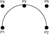
For U-bends, the P-points must be set as shown in Figure 10:1.: P-point Numbering Convention for U-bends.
|
|
Figure 10:1.
|
Refer to Setting Up ISODRAFT for further information.

