Compare/Update
User Guide
Options and Mapping : Options
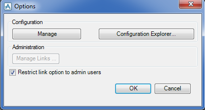
The types of elements that will be compared and how their attributes will be mapped are set using the Options window, from the main toolbar, select Options.
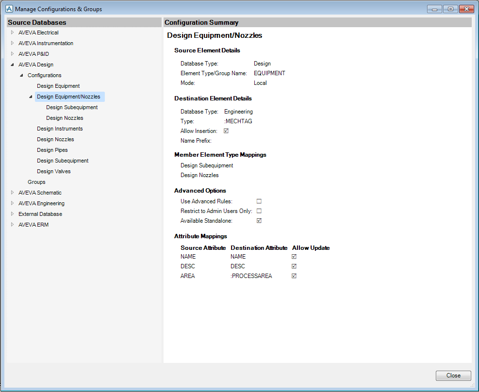
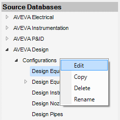
Use the Source Databases hierarchy to display the available databases, groups of configurations, parent and child configurations. Select a configuration to display its summary details in the right hand pane of the Manage Configurations & Groups window.
Alternatively, click Summary to display read only configuration summary details.
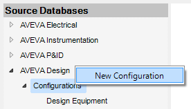
Right click one of the configurations nodes to create a new configuration with that source database.
Set Mode to Local if the source data is to be from a product installed on the same computer.
Set Mode to Service:
|
•
|
If the source data is to be from the AVEVA Integration Service. The window changes to show fields for Server Name, Port and Source. These should be set according to the Service configuration. An external relational database source is available (only in the service mode and not in 12.1 SP4) using a suitable configuration of the AVEVA Integration Service.
|
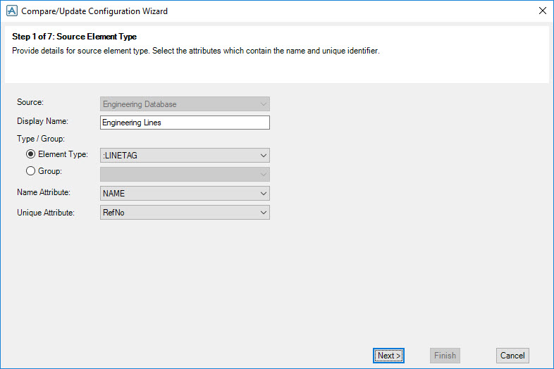
Select the Source database from the drop-down list. If the source is AVEVA Electrical, AVEVA Instrumentation or AVEVA P&ID, a Login button will appear. Click this and log in to the source system.
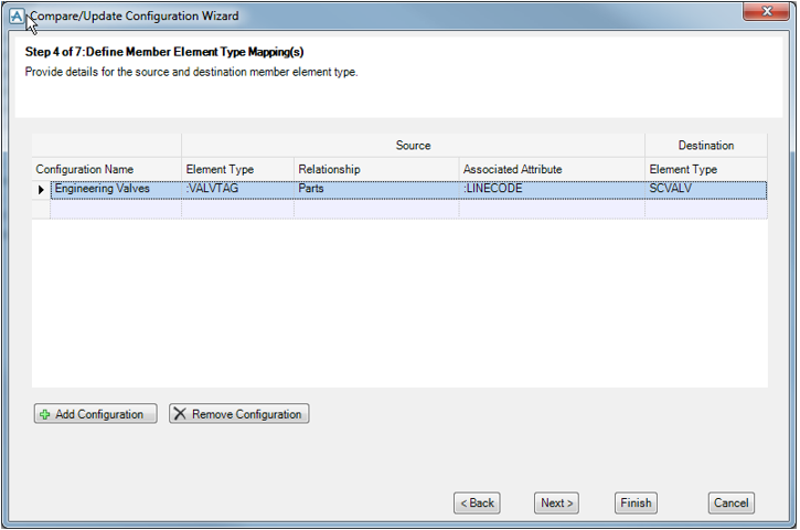
Either click on Element Type and select the type of object in the source database or click on Group and select one of the pre-defined source groups. Source groups will be available only in certain contexts such as Design Valves or Design Piping Specials where the group represents a combination of element types.
Select the Name Attribute that is to be used for name matching, and the Unique Attribute that is to be used for internal ids.
Click Next to continue.
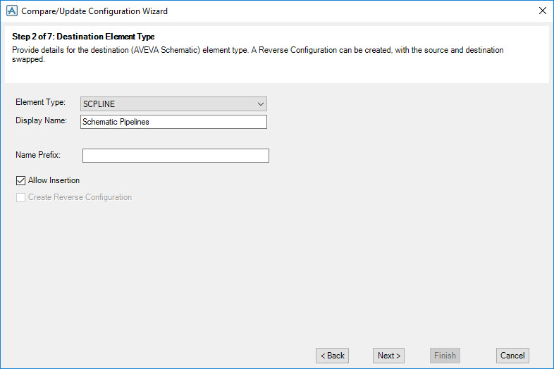
In Element Type select the type of object in the target database.
Enter the Display Name that will be used in the Attribute Mapping screen.
If Compare/Update finds unmatched objects, it can create corresponding new objects in the target database. Check Allow insertion if this is to be allowed.
By default, inserted objects take the same name as their source objects. An optional Name Prefix can be specified.
Check Create Reverse Configuration to automatically create a configuration with source and target swapped (this option will be available only when both are Dabacon databases).
Click Next to continue.
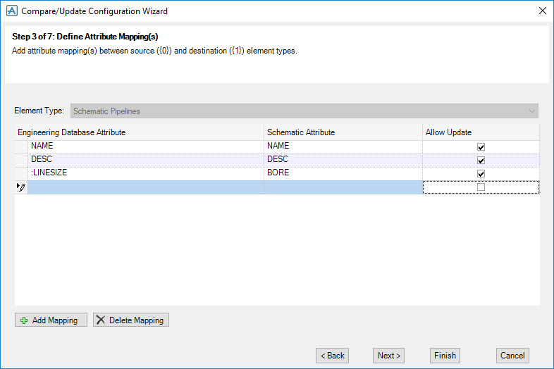
Click Add Mapping to add an empty attribute mapping row to the list. On the source side do one of the following:
Select to un check the Allow Update check box if the attribute is to be compared only and not updated.
Select a mapping row and click Delete to remove it.
Click Next to continue.
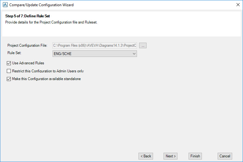
If advanced rules are required for this configuration, select a Project Configuration File (this will usually be the default filename for the project, for example: for Sample project this would be %SAMDFLTS%\ModelManagement\ProjectConfiguration.xml). Then select a Rule Set and check Use Advanced Rules.
Select the Restrict the Configuration to Admin Users only check box, if you want to test this configuration before publishing it for general use on the project.
Click Next to continue.
Select the Make this Configuration available standalone check box to allow end users to be able to run it when it is not part of a group of configurations.
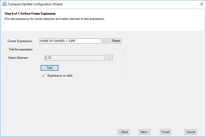
An optional Owner Expression can be entered. This will be evaluated against the appropriate source object during the Update Database process to determine the owner for an inserted object.
The expression can be tested by selecting an object of the appropriate source type and pressing Test.
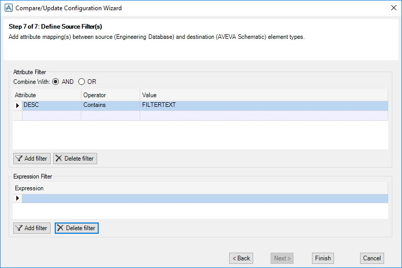
Two types of filters can be entered. The first is on attribute values. The second is on the evaluation of a PML expression. Click the appropriate Add Filter to add a row.
|
Note:
|
Multiple filters will be joined with AND when generating the query.
|
Click Finish to complete and save the configuration.
|
Note:
|
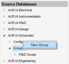
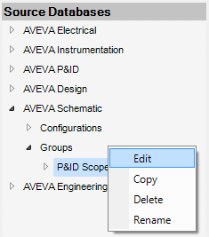
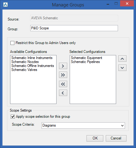
Use the Manage Groups window to choose which groups of configurations are to be compared.
Select the Restrict this Group to Admin Users only check box to test it before making it available to the project.
To enable scope selection click to select the Apply scope selection for this group check box and select the appropriate Scope Criteria from the drop down list.
Click OK to save the group.
Users who are members of team CUADMIN can set up advanced rules by clicking Configuration Explorer. This displays the Project Configuration Explorer shared with Schematic 3D Integrator. There you can configure more elaborate rules for element matching and updating, in particular key attribute mapping to match multiple pipes against schematic or engineering pipelines. An example set of rules using key attributes for engineering to design matching is included in the out of the box ProjectConfiguration.xml file. Refer to the Schematic 3D Integrator User Guide section on How to Configure Rules.
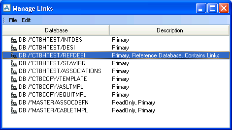
Users who are members of team CUADMIN can click on Manage Links to display this window:
|
Note:
|
The Manage Links window is shared between Integrator and Compare/Update. Design Reference databases can be written to by 3D, schematic and engineering users.
|
|
Caution: This operation should be used only when all of the databases holding objects that have been linked are current on the MDB.
|
|
The Edit menu provides Cut, Copy, Paste and Delete functions to move Link Worlds between databases. You can also drag and drop from one database to another to move or merge a Link World.
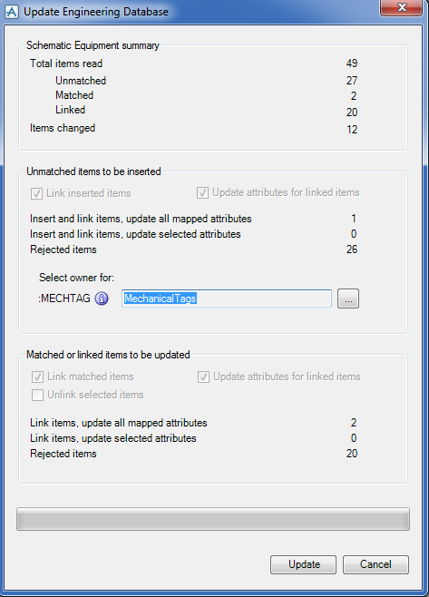
Use the Restrict link option to admin users functionality to control whether general users can change the Update Engineering Database settings for linking, updating attributes, and unlinking. If the option is checked, these settings are disabled, so that end users must use the default settings for link and update, and are not able to unlink.

