Diagrams
User Guide
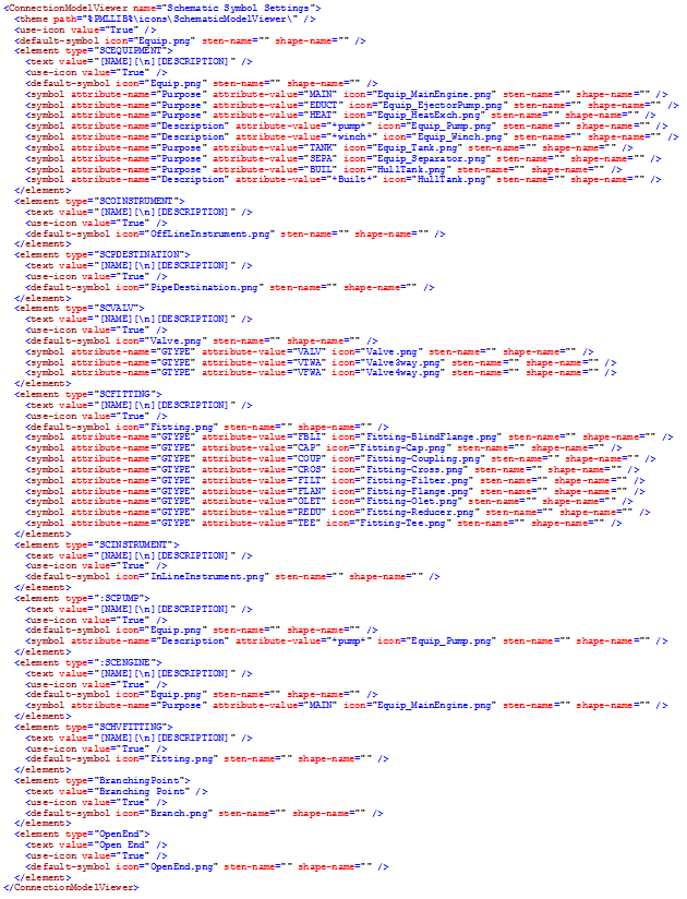
The icons used to represent the equipment items, generic branch points as well as inline fittings are determined by a set of user configurable rules. These rules are stored in an XML file called SchematicSymbols.xml which resides in the main installation directory.
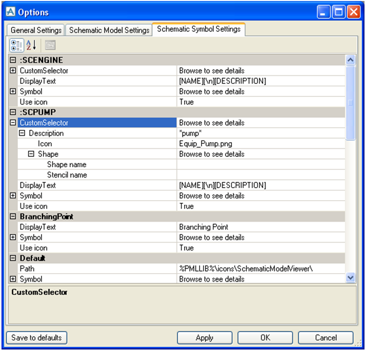
It is possible to determine which symbol should be used when creating a connection map and also to set the displayed text beneath the item. Attributes can be used by entering the attribute name in brackets, e.g. [Type]. To use a shape from a stencil instead of icons the setting ‘Use Icon’ needs to be set to False and the settings ‘Set Stencil Name’ and ‘Stencil Shape’ to True. However, if the system cannot find a shape or a stencil the icon will be automatically used instead. If an icon, a shape or a stencil is not found the default rule will be used.


