Diagrams
User Guide
Diagrams : Piping & Instrumentation Diagrams (P&IDs) : Creating Pipelines
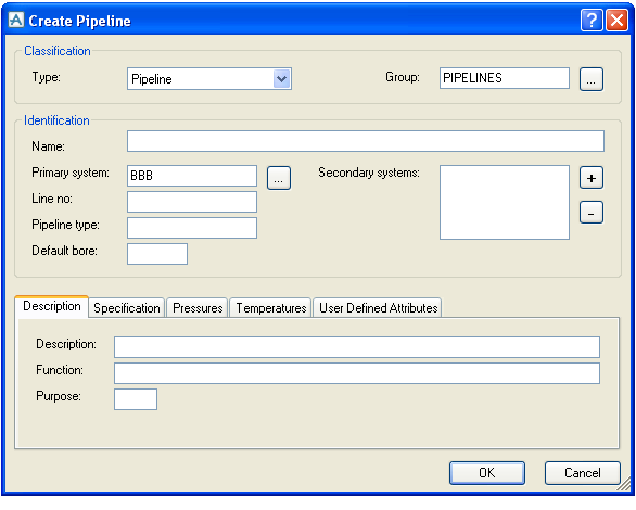
Pipelines can be created using the Home Tab > P&ID > Pipe > Create Pipeline command.
When the Create Pipeline dialogue is opened, a number of attributes will have values pre-set as follows. These are just default values and can be changed by the user.
|
•
|
|
•
|
The Type dropdown box will allow the user to create pipelines using derived UDET types.
The pipeline name can be automatically constructed by using the Autonaming function. In order to provide feedback on the autonaming while the dialogue is open, a pipeline element is actually created as the dialogue is opened. In case the user clicks Cancel, this pipeline element will be removed again.
It is also possible to move pipelines between schematic groups either by changing the Group in the Pipeline Properties dialogue, or by using the Cut and Paste commands in the Schematic Explorer.
|
Note:
|
That it is also possible to create pipelines by dropping a Pipeline shape onto the drawing. This works more or less like a Branch shape with the difference that it also creates a new pipeline (the Create Pipeline dialogue is automatically shown when the pipeline shape is dropped onto the drawing). Pipeline shapes can be created by using the Import Shape Wizard. See chapter Getting Started for further information.
|

